Get Parts Quote
Name
Company *
Phone *
Email *
Address
City
State / Province / Region
Zipcode
Country
Quantity *
Part Number *
Manufacturer
Preferred Condition
Additional Information
Cancel

X20AI2437

Analog Input Module
In Stock
Ships by Tuesday, September 22
Fast Shipping Available

Product Describe:

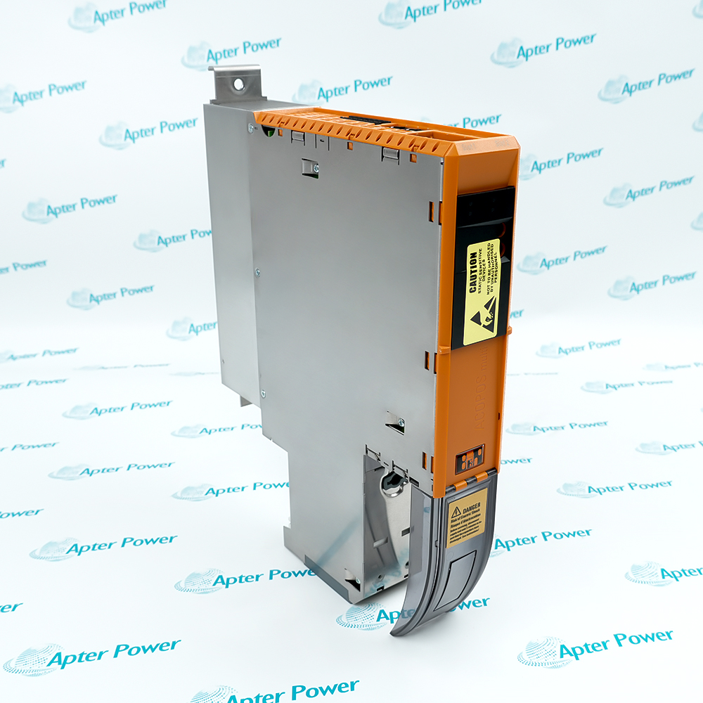
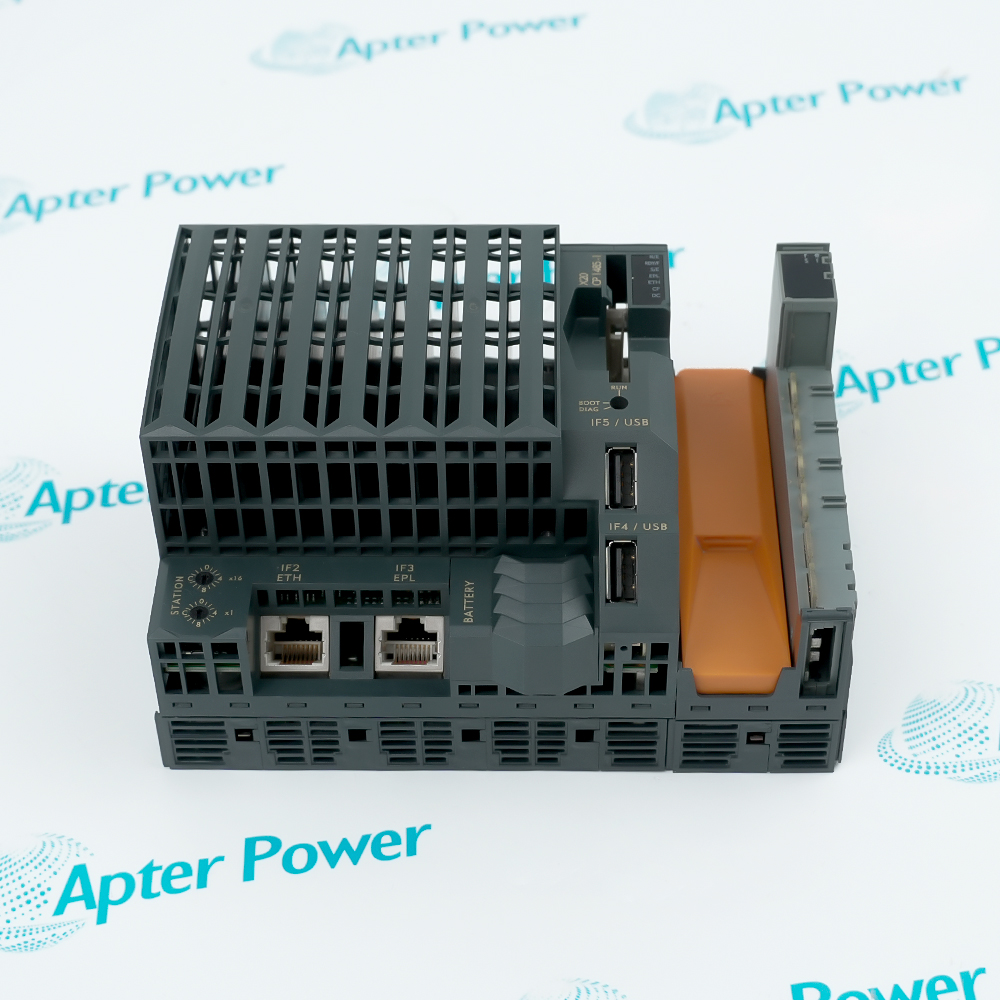
B&R X20AI2437 measures two current channels over selectable 4 to 20 mA or 0 to 25 mA ranges with 16-bit conversion. Each channel has an isolated sensor supply and supports NetTime measurement timestamps for synchronized acquisition.

Ask our team:

Get a quick price for: X20AI2437
Quantity*
Upload (gif, jpg, jpeg, png, bmp, doc, docx, xls, xlsx, ppt, pdf, csv)
For more information on how your data is processed and stored by Apterpower please read our privacy policy.

Technical specifications for X20AI2437

Technical specifications for X20AI2437

  • Manufacturer:
    B&R
  • Product Category:
    PLC Systems
  • Spare Part Number:
    X20AI2437
  • Estimated shipping dimensions:
    9.7x5.8x1.1cm
  • Weight:
    0.02 kg
  • Tariff Code:
    8537101190
  • Counliy of origin:
    Austria
  • Analog inputs:
    2 current measurement channels
  • Measurement ranges:
    4 to 20 mA or 0 to 25 mA
  • Converter resolution:
    16 bit
  • Sensor supply:
    One isolated supply per channel
  • Sensor supply voltage:
    25 V ±2%
  • Sensor supply current:
    30 mA maximum per channel
  • Sensor supply short circuit:
    Continuous protection with current limiting
  • Electrical isolation:
    Channel-to-channel and channel-to-bus
  • Bus power consumption:
    0.05 W
  • Internal I/O power:
    1.15 W
  • B&R ID code:
    0xB784
  • Protection rating:
    IP20
  • Operating temperature:
    -25 to 60 C horizontal; -25 to 50 C vertical
  • Required hardware:
    X20TB12 with X20BM11 or X20BM15

Information

Information

Overview Manuals Common Applications Product Precautions
B&R X20AI2437 measures two current channels over selectable 4 to 20 mA or 0 to 25 mA ranges with 16-bit conversion. Each channel has an isolated sensor supply and supports NetTime measurement timestamps for synchronized acquisition.
  • Acquires two industrial current loops with independent range selection
  • Supplies each connected transmitter from its own isolated 25 V source
  • Converts current signals with 16-bit digital resolution
  • Associates measurement timing with the documented NetTime function

Install B&R X20AI2437 with X20TB12 and X20BM11 or X20BM15, then configure the range for each channel. Verify sensor-supply polarity, loop current, isolation, timestamp behavior and the configured diagnostic response before release.

Important Notice: Confirm B&R X20AI2437, terminal hardware, field wiring, installed accessories and current B&R documentation before commissioning.

Apter Power B&R X20AI2437 Manuals and Guides
Apter Power B&R X20AI2437 Product and System Technical Reference PDFB&R X20AI2437 Official Data Sheet V1.40 PDF

Important Notice: The first document is an Apter Power model-specific technical reference; the second is the B&R official data sheet identified in the manufacturer source record.

Two-wire transmitter acquisition
B&R X20AI2437 powers and reads two isolated process transmitters in an X20 station.
Synchronized current measurement
NetTime identifies the measurement instant for controller-side correlation with other signals.
Mixed current-range retrofit
Each channel can use the documented 4 to 20 mA or 0 to 25 mA range required by the installed loop.
Isolated process monitoring
Channel-to-channel isolation limits unwanted coupling between independently powered field loops.
Read the applicable B&R instructions before work. Verify B&R X20AI2437 and the installed X20 System configuration.
1
Verify the complete B&R X20AI2437 marking and assigned channel numbers before work.
2
Place both process loops and their controlled equipment in the approved maintenance state.
3
Use X20TB12 with X20BM11 or X20BM15 and confirm terminal coding before insertion.
4
Record whether each channel is configured for 4 to 20 mA or 0 to 25 mA.
5
Check transmitter polarity and keep loop current within the selected measuring range.
6
Do not parallel the isolated sensor supplies or unintentionally common the field loops.
7
Prove sensor-supply short-circuit diagnostics and restore the loop without persistent fault.
8
Compare both measured currents and NetTime behavior with controlled reference signals before release.

Revisions

Revisions

Revision Part #

Also known as

Data sheet X20AI2437
B&R version 1.40, 2025-07-31

Alternative Names

Alternative Names

B&R X20AI2437

Technical notes

Technical notes

Install B&R X20AI2437 with X20TB12 and X20BM11 or X20BM15, then configure the range for each channel. Verify sensor-supply polarity, loop current, isolation, timestamp behavior and the configured diagnostic response before release.

FAQS

  • Which current ranges can B&R X20AI2437 measure?
    Each channel can be configured for either 4 to 20 mA or 0 to 25 mA operation.
  • How are the two B&R X20AI2437 channels isolated?
    B&R specifies channel-to-channel isolation and isolation between each channel and the bus; the sensor supply remains associated with its channel.
  • Can B&R X20AI2437 power two-wire transmitters directly?
    Yes. Each channel includes its own isolated nominal 25 V sensor supply rated up to 30 mA.
  • What happens if a B&R X20AI2437 sensor supply is shorted?
    The supply is continuously short-circuit proof and limits current, while diagnostics report the sensor-supply condition.
  • What does the NetTime function add to B&R X20AI2437?
    It provides the measurement time reference so acquired values can be correlated with other time-aware controller events.
  • Which accessories are mandatory for B&R X20AI2437?
    The product page requires one X20TB12 terminal block and one X20BM11 or X20BM15 bus module.
  • What temperature limits apply to B&R X20AI2437?
    Operation is specified from -25 to 60 C horizontally and -25 to 50 C vertically.
  • How should B&R X20AI2437 be accepted after replacement?
    Inject known currents on both channels, verify range scaling, sensor supplies, diagnostics, channel isolation and the configured timestamp behavior.
Trusted by 5,000+ plants worldwide | Backed by our vast inventory of top-tier control parts, modules and cards, fast shipments are dispatched to cover your urgent needs. ABOUT US >>
Disclaimer: We are not an authorized distributor or distributor of the product manufacturer of this website, The product may have older date codes or be an older series than that available direct from the factory or authorized dealers. Because our company is not an authorized distributor of this product, the Original Manufacturer`s warranty does not apply.While many DCS PLC products will have firmware already installed, Our company makes no representation as to whether a DSC PLC product will or will not have firmware and, if it does have firmware, whether the firmware is the revision level that you need for your application. Our company also makes no representations as to your ability or right to download or otherwise obtain firmware for the product from our company, its distributors, or any other source. Our company also makes no representations as to your right to install any such firmware on the product. Our company will not obtain or supply firmware on your behalf. It is your obligation to comply with the terms of any End-User License Agreement or similar document related to obtaining or installing firmware.

We’re Here When You Need Us

From product insights to customer service needs, our experienced service team will focus on getting you what you need quickly

Enquire

Complete our online form.

Call Us

Speak to one of our team.

Live Chat

Send us a message.