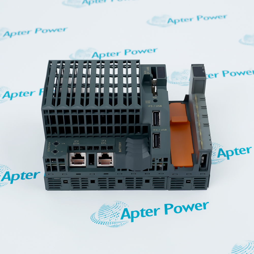
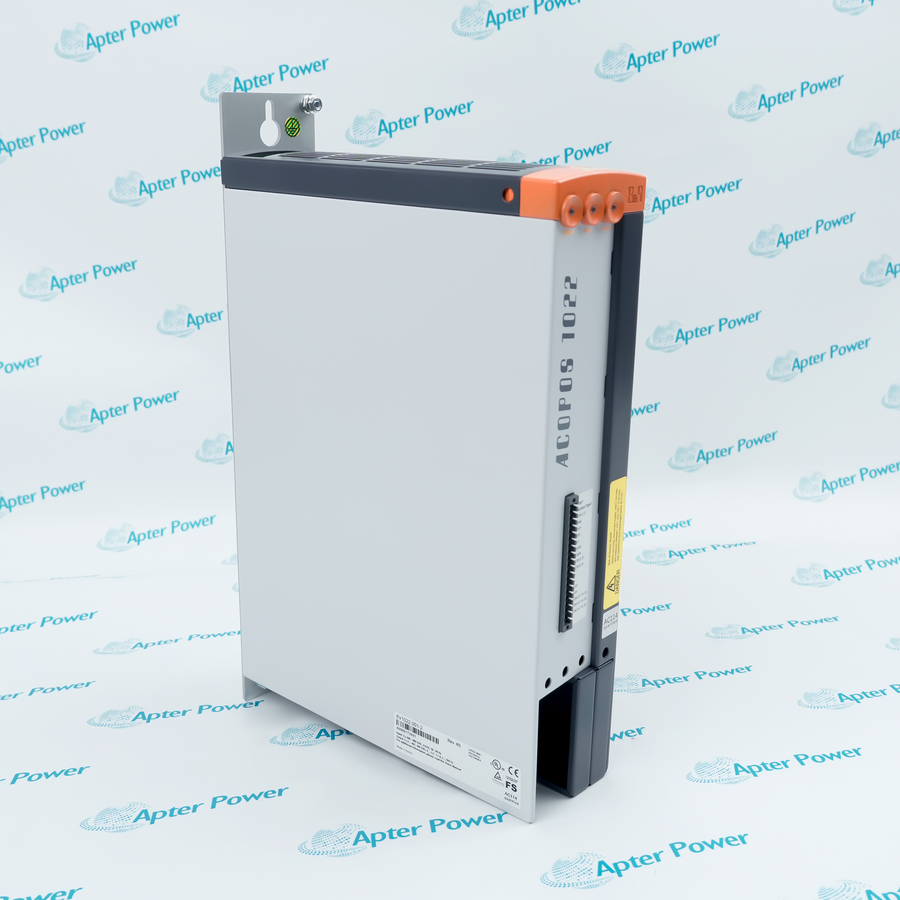
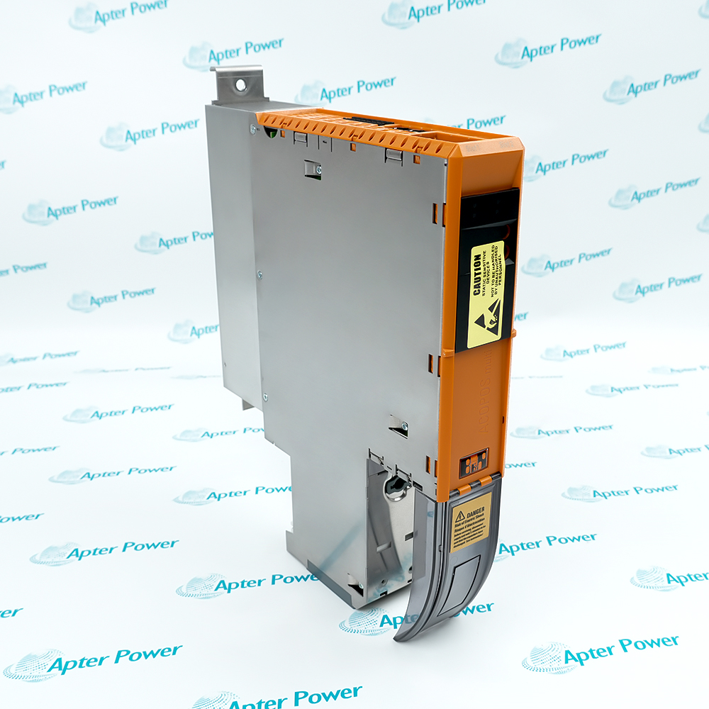
X20SC0842 operates with X20 safety bus base, 24 V DC safety field circuits, SafeLOGIC project, approved safety sensors and final elements.
Engineered applications include Emergency-stop input and output control, Guard-door safety monitoring, Safety-valve command, Distributed safety I/O renewal.
Important Notice: Confirm SafeDESIGNER channel mapping, test-pulse assignment, output load and proof-test sequence before enabling the safety application.
The first document presents model-specific engineering data. The second provides a separate installation, connection, commissioning and acceptance workflow.
Combines safe input evaluation with controlled shutdown outputs.
Monitors protective doors through the validated safety application.
Commands a documented safe final element within the channel rating.
Replaces the exact mixed module while retaining safety validation.
Verify the full X20SC0842 marking and its assigned B&R X20 safety I/O position before work.
Place the connected machine or process in the approved maintenance state.
Isolate the applicable supply and safe digital inputs and 24 v dc safety outputs field energy before disconnecting conductors.
Record connector, conductor, address and software identities before removal.
Use ESD controls and protect keyed interfaces, exposed contacts and electronic assemblies.
Confirm the installed X20 safety bus base and 24 V DC safety field circuits against the approved project.
Restore power in a controlled sequence and review device, network and host diagnostics.
Prove the intended emergency-stop input and output control function and retain the final test result.