Speak to a sourcing specialist
sales13@apterpower.com

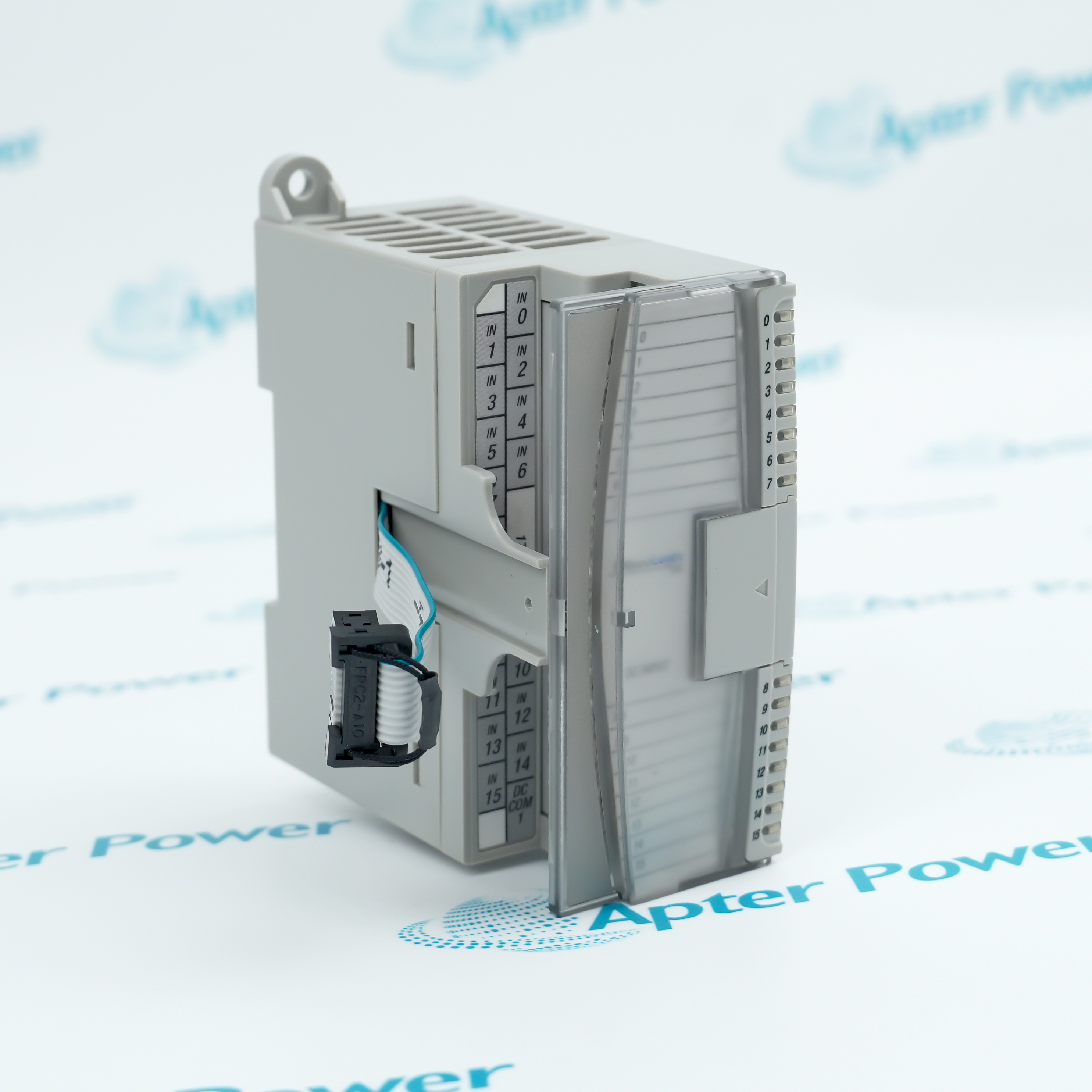
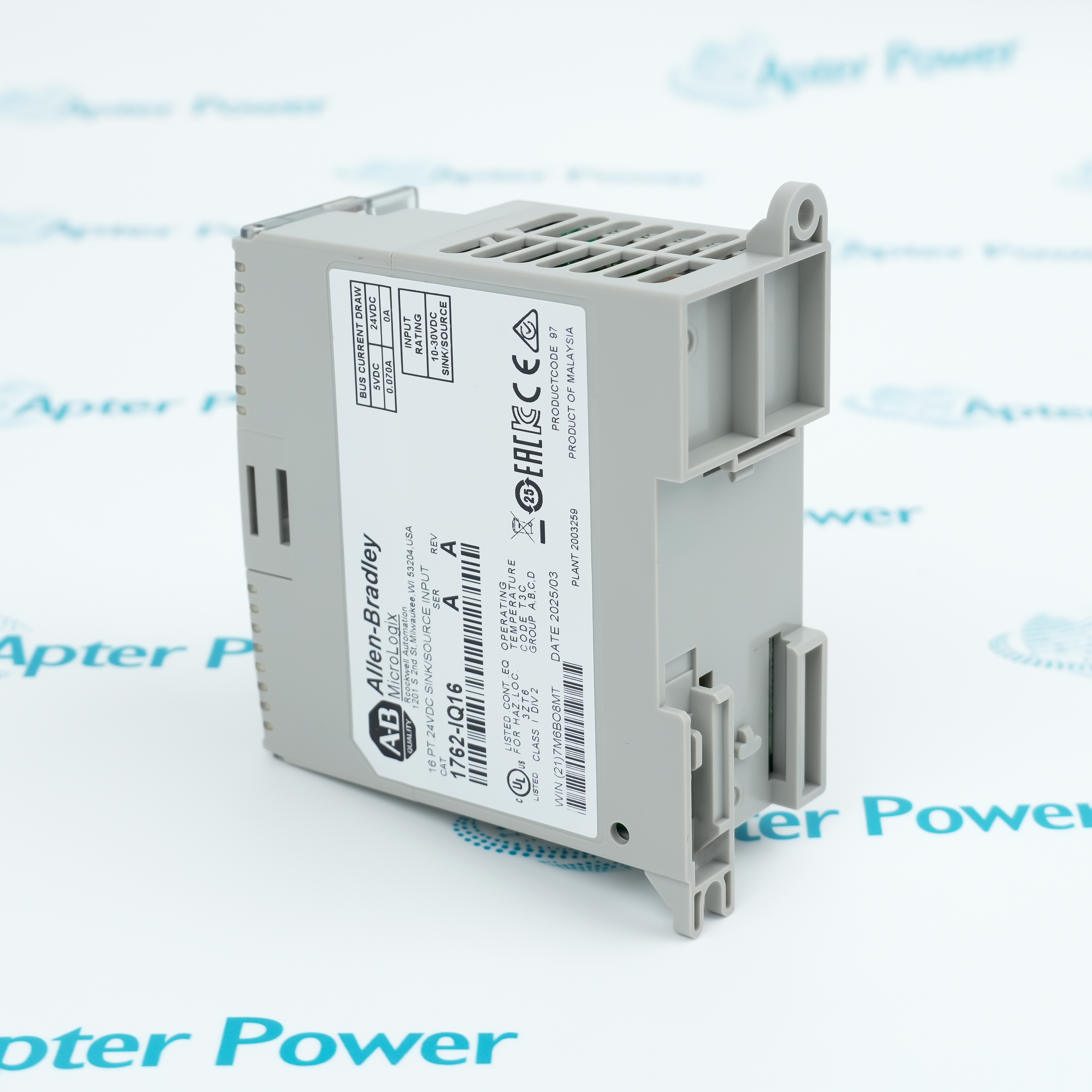
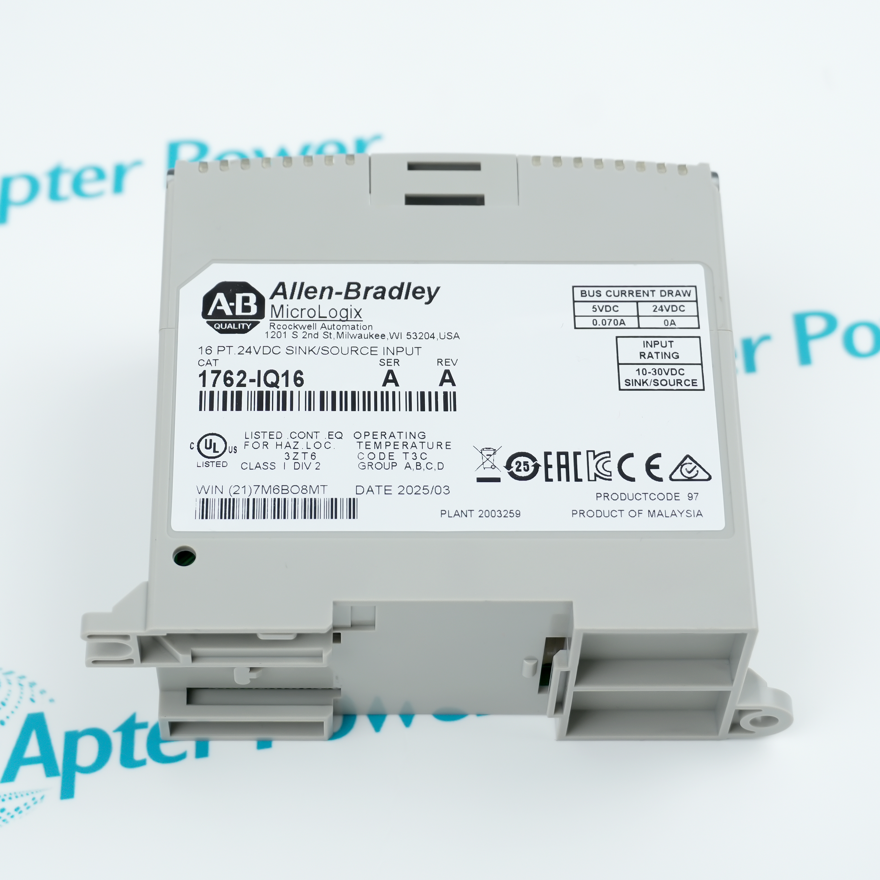
1762-IQ16

Sixteen-Point DC Digital Input Module
Allen-Bradley 1762-IQ16
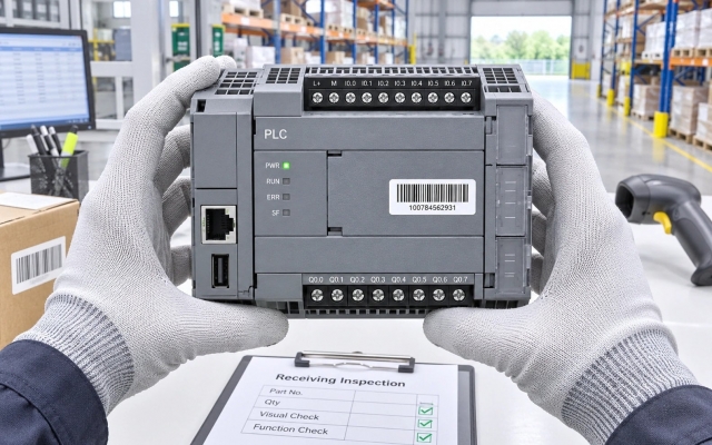
Product image is representative; revision or series may vary. Contact us to request a specific version.

Product Describe:

Allen-Bradley 1762-IQ16 adds discrete DC sensing to a compatible MicroLogix expansion system. Its sink/source input circuitry, grouped commons and per-point indication support conventional switches and powered field sensors.
  • Manufacturer part number
    1762-IQ16
  • Shipping
    Swift global dispatch
  • Condition
    New, original product
  • Shipping size (est.)
    17cm x 11cm x 5.3cm
  • Country of Origin
    USA
Get a quick price for 1762-IQ16
E-mail *
Mobile
Company
Content *
Quantity *
Upload (gif, jpg, jpeg, png, bmp, doc, docx, xls, xlsx, ppt, pdf, csv)
For more information on how your data is processed and stored by Apterpower please read our privacy policy

What happens after you enquire

  • 0

    Review your reference

    Send the full 1762-IQ16 reference, series, controller model and terminal photographs.

  • 1

    Confirm the offer

    Review the offered input module, connector condition and included mounting items.

  • 2

    Arrange dispatch

    Confirm quantity, delivery details and the agreed dispatch date before shipment arrangement.

  • Match the complete marking

    Include the complete 1762-IQ16 marking and series, host controller model and installed expansion-slot position.

  • Check the offered item before ordering

    Compare the offered 1762-IQ16 with field-device polarity, common groups, simultaneous input demand and cabinet temperature.

Technical specifications for 1762-IQ16

  • Manufacturer:
    Allen-Bradley
  • Product Category:
    PLC Systems
  • Spare Part Number:
    1762-IQ16
  • Weight:
    0.25 kg
  • Tariff Code:
    8537101190
  • Digital inputs:
    16
  • Input voltage category:
    24 V DC, sinking/sourcing
  • Input voltage envelope:
    10–30 V DC; 10–26.4 V DC subject to thermal point-count limits
  • Isolated input groups:
    Two groups of eight: 0–7 and 8–15
  • Maximum expansion-bus demand:
    70 mA at 5 V DC; 0.35 W
  • Maximum on-delay:
    8 ms
  • Maximum off-delay:
    8 ms
  • Maximum off-state voltage:
    5 V DC
  • Maximum off-state current:
    1.5 mA
  • Minimum on-state voltage:
    10 V DC
  • Minimum on-state current:
    2.0 mA at 10 V DC
  • Nominal on-state current:
    8.0 mA at 24 V DC
  • Maximum on-state current:
    12.0 mA at 30 V DC
  • Nominal input impedance:
    3 kΩ
  • Input-group/backplane test:
    1200 V AC for 1 s or 1697 V DC for 1 s
  • Working isolation voltage:
    75 V DC, IEC Class 2 reinforced insulation
  • Input data allocation:
    One read-only word; bits 0–15
  • Maximum heat dissipation at 30 V:
    5.4 W
  • Maximum heat dissipation at 26.4 V:
    4.3 W
  • Operating temperature:
    −20 to +65 °C; simultaneous-point derating applies
  • Nonoperating temperature:
    −40 to +85 °C
  • Relative humidity:
    5–95%, non-condensing
  • Maximum operating altitude:
    2000 m
  • Operating vibration:
    5 g, 10–500 Hz
  • Operating shock:
    30 g
  • Nonoperating shock:
    50 g panel-mounted; 40 g DIN-mounted
  • Terminal screw torque:
    0.90 N·m
  • Solid conductor range:
    0.34–2.5 mm² copper, 90 °C
  • Stranded conductor range:
    0.34–1.5 mm² copper, 90 °C
  • Required ventilation space:
    50.8 mm on all sides of the assembly
  • Mounting orientation:
    Horizontal only
  • Protection rating:
    IP20; installation enclosure required
  • Pollution degree:
    2
  • Overvoltage category:
    II
  • ESD immunity:
    4 kV contact/indirect; 8 kV air
  • Radiated RF immunity:
    10 V/m, 80–2700 MHz, 80% AM at 1 kHz
  • EFT immunity, signal ports:
    ±2 kV at 5 kHz
  • Surge immunity, signal ports:
    ±1 kV differential; ±2 kV common mode
  • Conducted RF immunity:
    10 V rms, 150 kHz–80 MHz, 80% AM at 1 kHz

Information

Overview Downloads Applications / Compatibility Product Precautions
  • Allen-Bradley 1762-IQ16 converts field switching states into a controller input word. Separate common groups allow circuit references to be planned by bank, while correct polarity, input duration and thermal loading determine whether the application receives reliable state changes.
Circuit grouping: Common assignments establish the current path for each connected sensor bank.
State visibility: Input indication supports comparison of field conditions with the controller data image.
Integration discipline: Electrical thresholds, input filtering and controller execution must be assessed together.
The two input banks use their own commons. Decide whether the field devices source or sink current before terminating either bank; separate group commons do not create isolation between every individual channel. The field supply, sensor output and module input must form a complete compatible circuit.

Input data is presented as a read-only word whose bits follow the physical terminal numbers. Expansion position is part of the address, so moving a module can change the meaning of existing logic even when all its field wires remain attached. Match the retained hardware configuration before commissioning.

The upper operating temperature is not an unconditional all-inputs-on rating. Input voltage and simultaneous active points determine the thermal allowance. Budget expansion-bus demand separately from field-device current, and allow for controller scan timing when assessing short sensor pulses.
Controller platform reference: MicroLogix 1762 expansion I/O. Match controller support, power budget, common-group wiring and input addressing.
The downloads for 1762-IQ16 separate original installation instructions from a point-by-point commissioning workbook. View PDF opens an independent engineering dossier covering input behavior, loading and thermal capacity.
Original manufacturer pages retain their technical context. Use the Apter Power guide with the applicable manufacturer instructions and approved installation design.
System and supply context: System compatibility: Use the module only in a supported MicroLogix 1762 expansion arrangement with an adequate controller power budget. Preserve the installed series, expansion position and field common allocation.

Application scope: Application scope: These examples concern ordinary discrete monitoring. The module is not a safety-rated input, and filtered process inputs should not be assumed to capture high-speed pulses.
Prepare Allen-Bradley 1762-IQ16 for its configured installation using these checks.
I

s

R

e

K

e

U

s

R

e

T

e

Alternative Names

Allen-Bradley 1762 IQ16 MicroLogix 16-point sink/source input expansion

Technical notes

Common-group boundary: Inputs 0–7 share the first bank; inputs 8–15 share the second. A missing common can affect a complete bank. Channel-level isolation must not be inferred from group isolation.

Pulse recognition: The module delay is only one part of the observation path. A field pulse must remain valid long enough for both the input circuit and the controller program to observe it.

Terminal work: Keep the fingersafe cover in place while wiring, secure the conductor under the pressure plate and apply the specified terminal torque. Inspect for loose strands before energization.

Thermal demand: At 26.4 V DC, the all-on allowance extends to 55 °C and decreases to 12 points at 65 °C. At 30 V DC, the chart permits 16 points at 30 °C, 10 at 55 °C and 8 at 65 °C. Use actual simultaneous states, not the average duty cycle.


FAQ View All FAQ

  • Why might a two-wire sensor keep an input of 1762-IQ16 on after the sensor switches off?
    Residual sensor current or an added indicator can keep the input above its off-state limits. Measure the actual off-state voltage and current with the sensor connected; select a compatible interface instead of assuming that a nominal 24 V sensor is suitable.
  • Would a 4 ms pulse be reliably captured by 1762-IQ16?
    Not from the module rating alone. The specified input on-delay can be as long as 8 ms, and controller scan timing adds another observation constraint. Use an approved pulse-capture or high-speed input solution when the event duration cannot satisfy the complete timing path.
  • Can sixteen active inputs remain on 1762-IQ16 at 26.4 V DC and 65 °C?
    No. The thermal chart permits twelve simultaneous points at that condition. Reduce the active-point load or change the approved thermal arrangement; do not average short inactive periods to justify an excessive simultaneous load.
  • What can explain a whole bank of 1762-IQ16 changing state together?
    Investigate the bank common, shared field supply and common wiring before suspecting eight independent sensor faults. Compare terminals 0–7 or 8–15 as a group, then check individual branches under controlled conditions.
  • Why can moving 1762-IQ16 one expansion position change which machine function responds?
    The expansion slot forms part of the controller input address. The terminal number still identifies the bit, but its slot prefix changes. Update and verify the hardware configuration and program references before returning the machine to service.
  • Does the 70 mA bus demand of 1762-IQ16 include its connected field sensors?
    No. That value is the module load on the 5 V expansion bus. Sensor and input-circuit demand belongs in the external field-supply budget. Calculate the two power paths separately and include all installed modules and devices.
  • Can an input-group isolation rating make 1762-IQ16 suitable for a 120 V AC field signal?
    No. The input is intended for the specified DC switching range. Dielectric test and working-isolation values do not expand its signal range; use a correctly rated input or approved interface for a different signal type.
  • Why should the protective debris strip be removed before operating 1762-IQ16?
    It protects the module during nearby mounting and wiring work, but leaving it in place restricts ventilation. Finish the work, inspect for wire strands or metal debris, and remove the strip before controlled energization.
SPEAK TO OUR TEAM
Let’s find the right solution for you.
Send us the part number, quantity and delivery destination. Our team will help confirm availability and lead time.
  • Whatsapp: +86 18030235313

    Send us a message.
  • sales13@apterpower.com

    Complete our online form.
  • +86 18030235313

    Speak to our team in your native language.