-
Match the complete marking
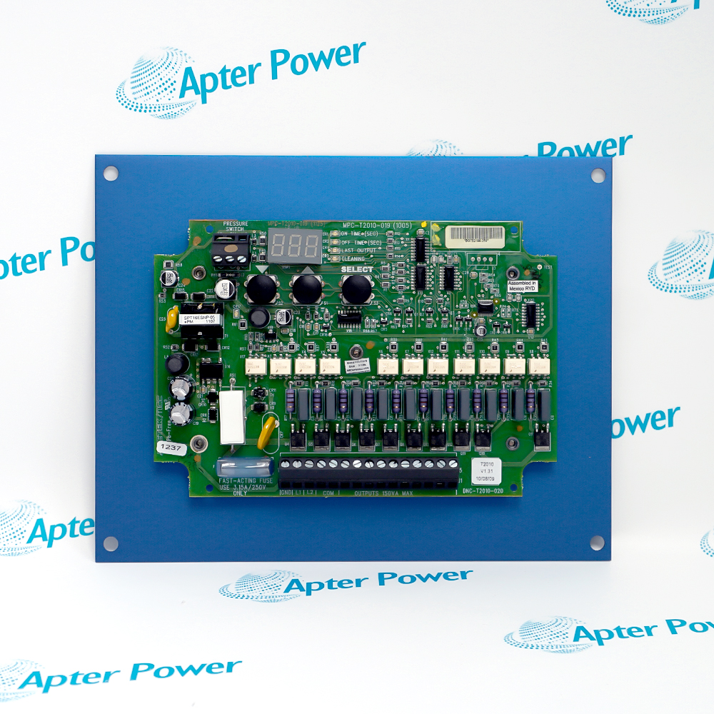
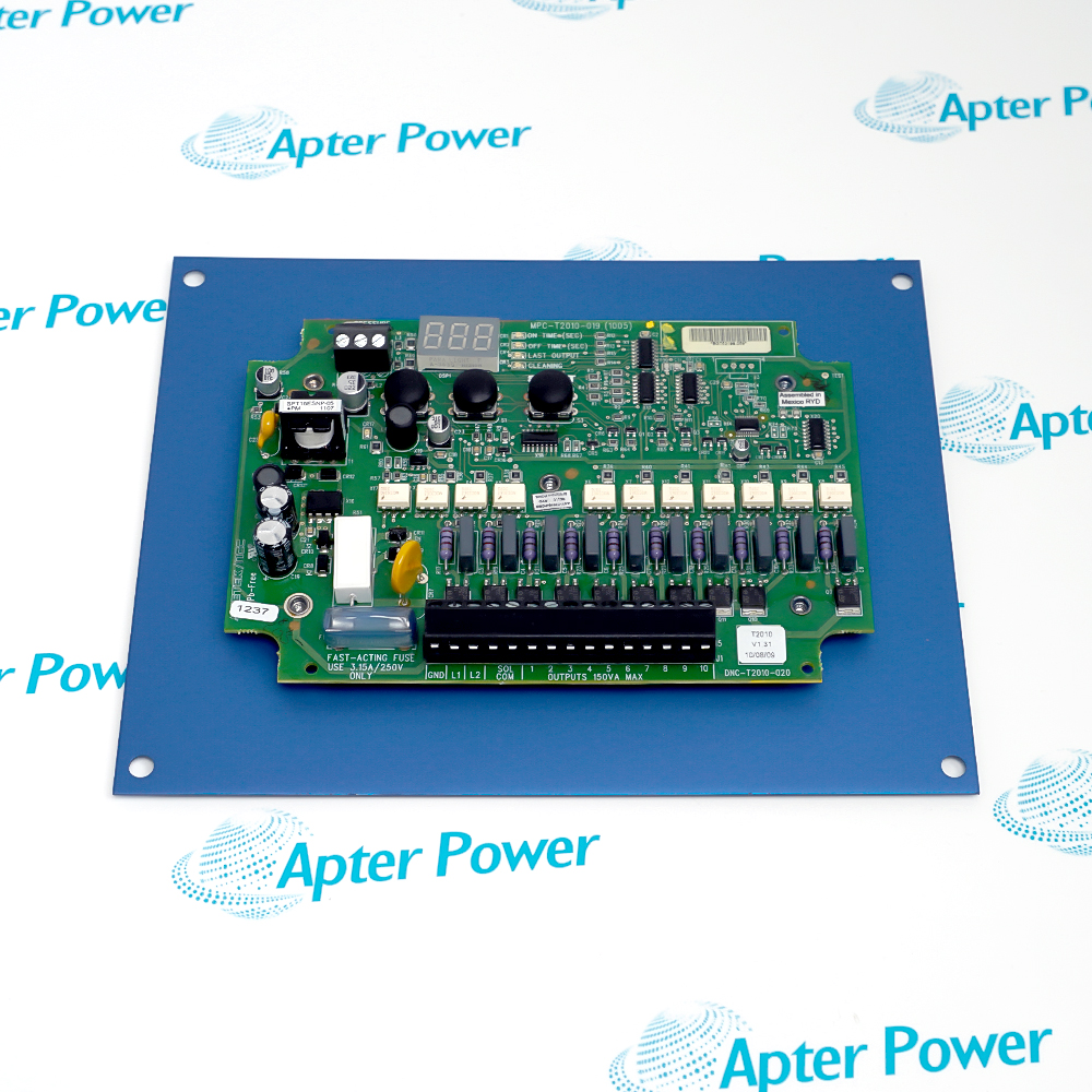
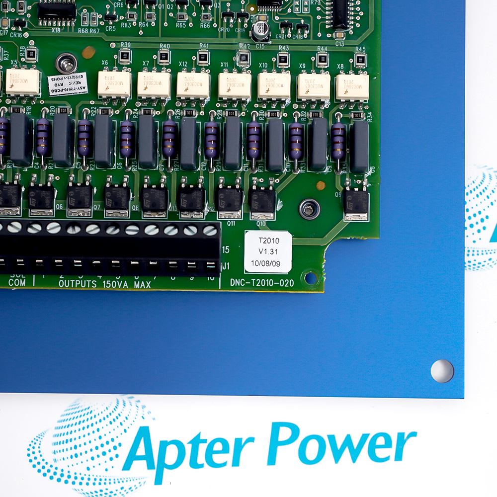
Record the complete DNC-T2010-R20 marking, including the R20 retrofit suffix and any controller revision shown on the unit. Keep that exact reference on the enquiry and quotation.
-
Check the offered item before ordering
Request available controller label, power-terminal and output-terminal photos. Have your maintenance team compare the offered DNC-T2010-R20 with the installed dust-collector control and applicable AMETEK documentation.
Technical specifications for DNC-T2010-R20
-
Manufacturer:AMETEK
-
Product Category:General Automation
-
Spare Part Number:DNC-T2010-R20
-
Weight:0.28 kg
-
Tariff Code:8537101190
-
Supply voltage:95–265 VAC, 50/60 Hz
-
Maximum outputs:10 solenoid positions
-
Selected output count:Programmable 1–10
-
On-time setting:0.050–0.600 s for DNC-T2010-R20
-
Off-time setting:1–999 s
-
Maximum output load:150 VA per output
-
Off-state leakage:1.5 mA maximum
-
On-state voltage drop:1.5 V maximum
-
Power consumption:6.30 VA maximum plus connected load
-
Input protection:3.15 A fast-acting fuse and 72 J MOV
-
Display:Three-digit, seven-segment green LED
-
Operating temperature:-40 to +66 °C
Information
- The controller advances solenoid outputs using programmed on time, off time and last-output settings. Pressure-switch contacts can initiate demand cleaning; the installed valve circuit and enclosure complete the system.
Retrofit path: R20 plate supports replacement of specified older DNC-T2010 controls
Demand input: Pressure-switch contacts govern cleaning in demand mode
Acceptance focus: Confirm every energized valve and the return to the first output
The exact replacement-chart row specifies 0.050–0.600 s on time and 1–999 s off time for DNC-T2010-R20. The broader family brochure describes the sequencer operation, three-button programming and a three-digit LED display; keep the exact R20 chart range when setting this part.
When high-pressure contacts close, the selected valve energizes for the on interval and remains off for the programmed off interval before the next selected output. Opening the contacts during an on interval completes that pulse. The unit is shipped with a jumper across the high-pressure switch input; confirm whether the installed collector uses continuous or demand cleaning.
-
AMETEK DNC-T2010-R20 original replacement chart
AMETEK National Controls Corp. chart - PDF, 1 page. Exact retrofit identity, output count and timing range. -
AMETEK DNC-T2010-R20 installation guide
Prepared by Apter Power - PDF, 5 pages. Identification, installation checks, commissioning and fault isolation.
Application scope: Use the retrofit plate and ten-output configuration in a documented DNC-T2010 cleaning circuit after checking supply, load and switch wiring.
-
Legacy controller replacement
Replace the listed DNC-T2010-A10 or B10 timing controller while retaining an approved field wiring schedule and checking the retrofit plate. -
Demand cleaning
Use the external pressure-switch input where the collector operates only when the configured pressure threshold calls for cleaning. -
Continuous cleaning
Use the high-pressure input jumper only where continuous sequencing is required by the installed operating plan. -
Valve-bank expansion within rating
Select the actual last connected output from 1 to 10, without energizing unused terminals or exceeding the documented valve load.
Disconnect the AC input and valve circuits before touching terminals; an open cabinet can expose hazardous voltage.
Do not power the controller from a converter or inverter; review high transient-voltage sites for the specified isolation transformer arrangement.
Confirm solenoid voltage and apparent power against the solid-state 150 VA output rating and account for off-state leakage.
Record the high/low pressure-switch contacts and factory jumper position before removing the prior controller.
Use the R20 retrofit hole pattern and a protective cabinet where dust, corrosion or vibration require it; avoid high-vibration mounting without shock mounts.
Run the controller test mode and prove each selected valve, on interval, off interval and demand stop before normal service.
Alternative Names
Technical notes
Installation relationship: The controller switches external pulse valves in sequence; AC supply, valve bank and demand pressure switch form the complete circuit.
Electrical limits: Confirm voltage and solenoid load against the AMETEK ratings before energizing the R20 retrofit unit.
Technical reference: AMETEK National Controls Corp. DNC-T2010-R20 replacement chart and Dust Collector Controls AC Input brochure, 618PDF (240037). Use the exact-model timing row for R20.

FAQ View All FAQ
-
How does DNC-T2010-R20 differ from a DNC-T2010-020 mounting arrangement?The R20 version uses a retrofit mounting plate for older DNC-T2010 positions. Check the existing hole pattern and enclosure clearance; the 020 standard plate should not be assumed to fit the same opening.
-
What must be checked before DNC-T2010-R20 replaces an A10 or B10 controller?Confirm the old full code, AC supply, solenoid voltage and load, terminal schedule, valve count and pressure-switch arrangement. Then restore the required on/off timing using the R20 range shown in AMETEK’s replacement chart.
-
How is the last active valve selected on DNC-T2010-R20?Use the Select control to reach the last-output parameter, then set the connected valve count from 1 through 10 with Up or Down. Verify that the sequence wraps to output 1 after the selected last output.
-
Why may DNC-T2010-R20 run continuously without a pressure-switch demand?AMETEK ships the control with a jumper across the high-pressure switch input. A closed high-pressure input allows continuous cycling, so compare the jumper and switch contacts with the collector operating plan.
-
What happens if the pressure-switch contacts open during a DNC-T2010-R20 pulse?The active output completes its programmed on interval. Cleaning then stops; on the next high-pressure closure, the sequencer advances to the next output in the selected sequence.
-
How can individual DNC-T2010-R20 outputs be checked during maintenance?Enter the documented test mode from normal operation, select each output with Up or Down and use Select to pulse it for the configured on time. Isolate the process and follow the site valve-test procedure.
-
Why should an LED or high-impedance test input not be used alone to judge a DNC-T2010-R20 output?The solid-state output has specified off-state leakage of up to 1.5 mA. Verify a suspected output with the actual compatible load or an approved test method, and check the valve wiring and supply first.
-
Which timing limits apply to the exact DNC-T2010-R20 retrofit model?The DNC-T2010-R20 row in the replacement chart gives 0.050–0.600 s on time and 1–999 s off time. Use those exact-model limits when transferring settings from the older A10 or B10 device.
Supporting new and legacy automation
-
Please try to be as accurate as possible with your search.
-
We can quote you on 1000s of specialist parts, even if they are not listed on our website.
-
We can't find any results for “”.
Related cases and sourcing guidance
View all case studiesYou May Also Like
Product Browsing History
-
Whatsapp: +86 18030235313
Send us a message. -
sales13@apterpower.com
Complete our online form. -
+86 18030235313
Speak to our team in your native language.