Speak to a sourcing specialist
sales13@apterpower.com
Get a quick price for RLY4 2500M/RLY4/XXXXX/XXXXXX
E-mail *
Mobile *
Company
Content *
Quantity *
Upload (gif, jpg, jpeg, png, bmp, doc, docx, xls, xlsx, ppt, pdf, csv)
For more information on how your data is processed and stored by Apterpower please read our privacy policy

What happens after you enquire

  • 1

    Requirement review

    We review the part number, quantity and delivery requirements and ask for any missing details.
  • 2

    Quotation and availability

    We confirm the proposed item, condition, availability, price and estimated lead time in the quotation.
  • 3

    Order confirmation and dispatch

    Once the quotation and purchasing details are agreed, your contact will coordinate the order and available dispatch information.

Technical specifications for RLY4 2500M/RLY4/XXXXX/XXXXXX

  • Manufacturer:
    Invensys
  • Product Category:
    DCS Systems
  • Spare Part Number:
    RLY4 2500M/RLY4/XXXXX/XXXXXX
  • Estimated shipping dimensions:
    2.6×8.8×9cm
  • Weight:
    0.12 kg
  • Tariff Code:
    8537101190
  • Counliy of origin:
    USA
  • Output channels:
    4
  • Channels 1–3 contact form:
    Normally open (NO)
  • Channel 4 contact form:
    Changeover (CO)
  • Output functions:
    On/off; time-proportioned; valve raise/lower
  • Terminal-unit screw terminals:
    12
  • Contact suppression:
    Removable RC snubbers
  • Snubber network:
    22 nF + 100 Ω across NO contacts

Information

Overview Manuals Common Applications Product Precautions
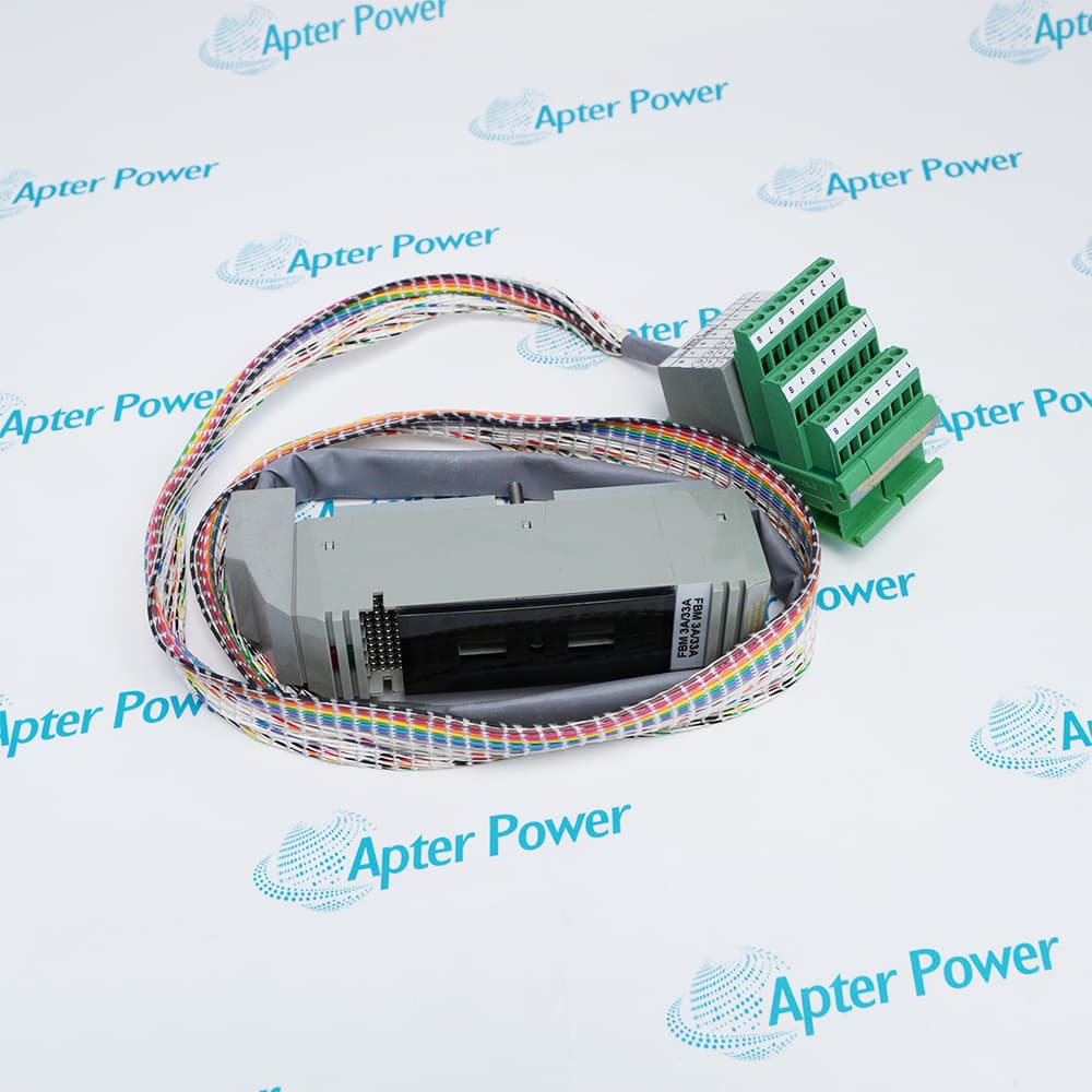
Foxboro RLY4 2500M/RLY4/XXXXX/XXXXXX provides contact outputs for on/off commands, time-proportioned control and valve raise/lower functions within a configured 2500 station.
  • Channels 1–3 have normally open contacts.
  • Channel 4 provides a changeover contact.
  • Separate relay circuits isolate the output channels.
  • Contact snubbers reduce arcing when switching inductive loads.

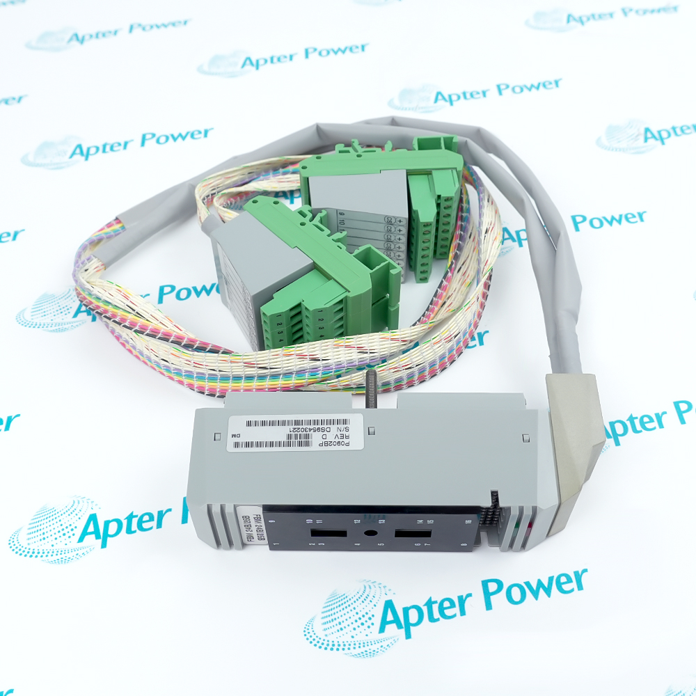
Field wiring lands on the relay terminal unit beneath the module. Its normally open and changeover terminals serve different circuit functions, so the load schedule must identify the contact path used by each channel.

Important Notice: Verify the open-contact state at the load itself, including any residual current through suppression components.

Foxboro RLY4 2500M/RLY4/XXXXX/XXXXXX Manuals & Downloads
Foxboro RLY4 2500M/RLY4/XXXXX/XXXXXX Manufacturer Technical Reference — Selected Pages (PDF)Foxboro RLY4 2500M/RLY4/XXXXX/XXXXXX Installation & Commissioning Guide (PDF)

The manufacturer excerpt covers the module connection and operating principles. The installation guide provides a separate sequence for wiring and functional checks.


Alarm contact outputs
Switch an external indication circuit from the configured station alarm logic.
On/off actuator commands
Provide relay contact operation for a suitably rated external load.
Time-proportioned control
Apply the configured duty-cycle command through a relay output.
Valve positioning
Use the assigned raise/lower output pair in a compatible valve-control circuit.
Prepare the affected circuits before installing Foxboro RLY4 2500M/RLY4/XXXXX/XXXXXX.
1
Identify the field supply feeding every relay common.
2
Isolate all load circuits before touching the terminal unit.
3
Distinguish the changeover channel from the three NO channels.
4
Evaluate inductive-load derating before connecting a coil.
5
Check snubber leakage against the load holding current.
6
Retain the designed suppression components for each circuit.
7
Verify both open and closed contact behavior with the load isolated.
8
Confirm the final actuator or alarm state before returning control to service.

Technical notes

The fitted snubbers pass a small AC current even when their relay contacts are open. Low-current loads can therefore remain energized unless the suppression arrangement is suitable for the connected circuit.

FAQ View All FAQ

  • Why can a small AC load remain energized after RLY4 2500M/RLY4/XXXXX/XXXXXX opens its relay?
    The suppression network carries leakage current across the open normally open contact. A load with a very low holding current can respond to that current.
  • Which RLY4 2500M/RLY4/XXXXX/XXXXXX channel provides both normally open and normally closed paths?
    Channel 4 uses a changeover contact. The first three channels provide normally open switching.
  • Can RLY4 2500M/RLY4/XXXXX/XXXXXX operate a time-proportioned output?
    Yes. Its output channel functions include time-proportioned operation as well as simple on/off and valve raise/lower control.
  • How does an inductive load affect contact selection for RLY4 2500M/RLY4/XXXXX/XXXXXX?
    Inductive loads increase switching stress and may require derating and appropriate suppression. A resistive-load current rating alone does not establish suitability for an inductive circuit.
  • Where are the load conductors connected for RLY4 2500M/RLY4/XXXXX/XXXXXX?
    The conductors connect to the relay terminal unit. Trace the channel common and selected contact terminals before attaching the load.
  • What must be isolated before exchanging RLY4 2500M/RLY4/XXXXX/XXXXXX?
    Isolate the field supply to the affected relay circuits as well as any other source that can energize the terminals. Removing module power alone does not prove the load wiring is dead.
Related reading

Related cases and sourcing guidance

View all case studies
SPEAK TO OUR TEAM
Let’s find the right solution for you.
Send us the part number, quantity and delivery destination. Our team will help confirm availability and lead time.
  • Whatsapp: +86 18030235313

    Send us a message.
  • sales13@apterpower.com

    Complete our online form.
  • +86 18030235313

    Speak to our team in your native language.