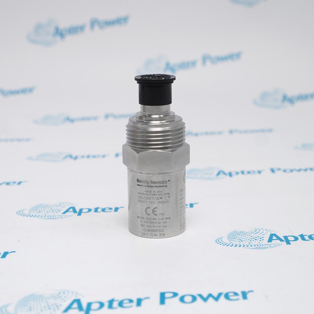
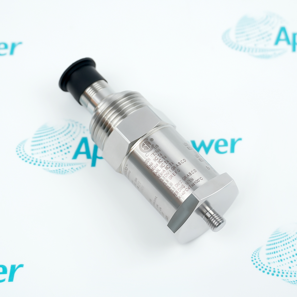
Technical specifications for 190501-21-00-01
-
Manufacturer:Bently Nevada
-
Product Category:Machinery Monitoring Systems
-
Spare Part Number:190501-21-00-01
-
Weight:0.35 kg
-
Tariff Code:8537101190
-
Product series:190501 Velomitor CT
-
Measured quantity:Casing vibration velocity
-
Mounting option 21:3/8-24 to 1/2-14 NPT adapter
-
Connection option 00:MIL-C-5015 connection interface
-
Approval option:01; verify supplied marking and installation conditions
-
Sensitivity:3.94 mV/mm/s (100 mV/in/s), ±5%
-
Frequency response (±1 dB):3 Hz to 900 Hz
-
Frequency response (±3 dB):1.5 Hz to 1 kHz
-
Peak velocity range:63.5 mm/s (2.5 in/s)
-
Transverse response:Less than 5% of axial sensitivity
-
Amplitude linearity:±2% to 63.5 mm/s peak
-
Output bias:10.1 V dc ±1.0 V dc, Pin A relative to Pin B
-
Dynamic output impedance:Less than 400 ohms, typical
-
Broadband noise (1.5 Hz-1 kHz):0.229 mm/s (0.009 in/s) peak
-
Electronics grounding:Isolated from case
-
Operating temperature:-40 °C to +85 °C
-
Storage temperature:-40 °C to +100 °C
-
Case material:316L stainless steel
-
Connector construction:2-pin 316L stainless steel, top-mounted
-
Mounting torque:4.5 N m ±0.6 N m
-
Mounting orientation:Any orientation
-
Humidity limit:100% condensing, non-submerged
-
Shock limit:5000 g peak, maximum
Information
- Slow fan rotation produces vibration at frequencies below the useful range of many general-purpose casing sensors. Bently Nevada 190501-21-00-01 extends velocity measurement into this low-frequency region for cooling-tower and air-cooled heat-exchanger fans.
Velocity sensitivity: 3.94 mV/mm/s, ±5%
Connection arrangement: Top-mounted two-pin MIL-C-5015 interface
Housing construction: 316L stainless steel case
The sensor can also measure the vibration frequencies generated by the fan motor and speed reducer. Evaluate the required frequency band, mounting arrangement and signal-conditioning channel together before commissioning.
Velomitor CT technical excerpt
6-page manufacturer-original excerpt: 141636 Rev. AF, pages 1-3 and 6-8, covering sensor specifications, ordering options and accessories.Installation preparation & verification
2-page Apter Power guide for 190501-21-00-01: configuration review, installation preparation and post-work verification. Not a manufacturer-issued manual.
Platform applications: Select the measurement point, frequency band and monitoring channel for the actual fan, motor or speed-reducer arrangement. Confirm the supplied approval marking and site installation conditions before use.
-
Cooling-tower fans
Measure casing vibration velocity on fan assemblies operating at or above 90 rpm. Choose a mounting point with a suitable vibration transmission path from the rotor. -
Air-cooled heat exchangers
Use low-frequency velocity measurement on heat-exchanger fan assemblies. Check the fan speed range and the structural response at the selected bearing housing or casing. -
Fan motor monitoring
Observe motor-generated vibration as part of the fan assembly measurement. Select the channel frequency band and mounting location for the diagnostic task. -
Speed-reducer vibration
Measure vibration transmitted from the fan speed reducer to the mounting location. Interpret readings with the gearbox configuration and its mechanical transmission path.
Mount on the bearing housing or casing where rotor vibration is transmitted effectively. Avoid flexible covers or locations dominated by unrelated structural motion.
Confirm the option 21 interface: 3/8-24 to 1/2-14 NPT. Verify the machine connection and adapter engagement before fitting the sensor.
Use the specified 4.5 N m ±0.6 N m sensor mounting torque with the applicable installation procedure; do not transfer it to unrelated pipe fittings.
Identify Pin A and Pin B and use the appropriate MIL-C-5015 mating connection. Select cable length and routing for the actual channel and installation conditions.
Keep the sensor within -40 °C to +85 °C in operation. Condensing humidity does not permit submersion; check the supplied approval marking separately.
Check bias, velocity scaling, frequency band and response using an approved procedure. Assess high-frequency acceleration that could reduce the usable velocity range.
Alternative Names
Technical notes
Reference conditions: Electrical parameters apply at +20 °C to +30 °C and 100 Hz unless otherwise stated. Vibration above 1 kHz exceeding 10 g peak can significantly reduce the stated velocity range.
Connection and installation: Pin A is positive relative to Pin B for velocity from the base toward the top. Apply the user guide 125389 and the approved site procedure; confirm hazardous-area marking and installation drawing for the supplied unit.

FAQ View All FAQ
-
What does mounting option 21 mean for 190501-21-00-01?It specifies a 3/8-24 to 1/2-14 NPT mounting adapter. Match the machine interface and the actual supplied adapter before installation; connection option 00 separately identifies the MIL-C-5015 electrical interface.
-
How does 190501-21-00-01 measure low-speed fan vibration?It measures casing vibration velocity with a response of 1.5 Hz to 1 kHz within ±3 dB. A suitable bearing-housing or casing mounting location must transmit rotor vibration effectively; the sensor is intended for fan assemblies operating at or above 90 rpm.
-
Which limits affect the 190501-21-00-01 velocity range?The specified range is 63.5 mm/s peak. Vibration components above 1 kHz exceeding 10 g peak can significantly reduce that range, so assess the high-frequency environment as well as the velocity level.
-
What cable and accessories are included with 190501-21-00-01?The order uses connection option 00, the MIL-C-5015 interface, rather than option 99 with an included 32-foot cable. Supply scope is confirmed in quotation; have the adapter, mating cable, connector accessories and documents listed individually.
-
Can photos verify the offered 190501-21-00-01 configuration?Request current nameplate, connector, mounting-base and adapter photos. Compare the full order code, serial marking and approval marking with the installed requirement, and record the agreed configuration and New, original product condition in the quotation.
-
How can I confirm the dispatch schedule for 190501-21-00-01?Send the required quantity, destination and required date. Confirm the available quantity, planned dispatch date and whether lead time starts from order acceptance or payment; a delivery estimate does not establish that units are in stock.
-
Which approval documents should accompany 190501-21-00-01?Specify the documents required by the intended installation and match them to the supplied approval marking. Confirm availability of the relevant certificate, instructions and any requested inspection records in the quotation; an approval option alone does not include a document package.
-
What warranty applies to 190501-21-00-01 and its accessories?Have the warranty period, scope, exclusions and claim process confirmed in the offer. Clarify coverage for the transducer and any separately quoted adapter or cable, and review installation-related exclusions before placing the order.
Supporting new and legacy automation
-
Please try to be as accurate as possible with your search.
-
We can quote you on 1000s of specialist parts, even if they are not listed on our website.
-
We can't find any results for “”.
You May Also Like
Product Browsing History
-
Whatsapp: +86 18030235313
Send us a message. -
sales13@apterpower.com
Complete our online form. -
+86 18030235313
Speak to our team in your native language.