-
Check the offered item before ordering
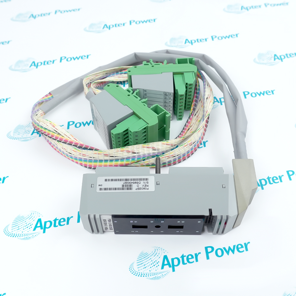
Please request current front, rear and identification-label photos of Foxboro FBM202 P0914ST. Have your maintenance team compare the complete marking, thermocouple and millivolt input module connections and installed configuration with the manufacturer documents before ordering.
-
Dispatch Confirmation
Quantity and dispatch date are confirmed in the quotation.
Technical specifications for FBM202 P0914ST
-
Manufacturer:Invensys
-
Product Category:DCS Systems
-
Spare Part Number:P0914ST
-
Weight:0.3 kg
-
Tariff Code:8537101190
-
Process input channels:Eight thermocouple or millivolt inputs
-
Reference-junction input:One isolated RTD channel
-
Channel isolation:Each process input galvanically isolated
-
Thermocouple diagnostic:Up-scale burnout detection
-
Conversion method:Per-channel sigma-delta conversion
-
Reading capability:New analog readings every 25 ms
-
Noise control:Configurable integration period
-
Application option:Configurable rate-of-change limits
-
Termination options:DIN-rail or paired-slot baseplate TA
-
Baseplate marking:P0914ST in the cited arrangement
Information
- FBM202 P0914ST commissioning depends on the configured sensor types and reference-junction arrangement.
Engineering boundary: Reference-junction arrangement is a separate path
Acceptance focus: Compare measured values with known references
P0914ST is shown in the manufacturer baseplate arrangement for this module. Thermocouple type, millivolt range and cold-junction method are configured in the system; the matched termination assembly and sensor wiring determine the installed measurement path. The separate RTD reference channel measures terminal temperature for thermocouple compensation; its wiring and location are part of the accuracy chain.
For replacement, save every channel type, scaling, compensation arrangement and alarm setting. Recommission with known input references and compare the displayed engineering values with the process instruments. An up-scale burnout indication may point to an open sensor path. Confirm the configured sensor type and termination before treating it as a process temperature.
-
Foxboro FBM202 P0914ST technical reference
Foxboro PSS excerpts: eight low-level inputs, isolated RTD reference path, burnout behavior and P0914ST baseplate context. PDF, 3 pages. -
Foxboro FBM202 P0914ST installation guide
Apter Power guide: retain sensor setup and compensation, then test inputs with known references. PDF, 3 pages.
Application scope: Check the baseplate, sensor type and reference-junction RTD path; conversion settings and terminal temperature compensation control the usable measurement.
-
Process temperature inputs
Acquire configured thermocouple measurements from supported field sensors. Select the thermocouple type and compensation path in the control configuration. -
Low-level voltage inputs
Read suitable millivolt signals within the configured range. Use the specified low-level voltage input range rather than assuming current-loop interchangeability. -
Cold-junction compensation
Use the paired RTD channel where the installed thermocouple arrangement requires reference compensation. The RTD measures terminal temperature for the thermocouple reference junction. -
Module restoration
Transfer a matched FBM202 while retaining the baseplate and channel configuration. Use known references to verify conversion and alarming after restoring the matched baseplate connection.
Record each thermocouple or millivolt selection. Mixed sensor types can need different scaling and burnout handling.
Keep low-level input leads and terminal polarity correct. Reversed thermocouple polarity can produce plausible but wrong trends.
Inspect the RTD reference path and its installation. A failed compensation path can shift several thermocouple readings.
Maintain shielding and separation from power cables. Low-level signals are sensitive to induced noise and grounding errors.
Confirm the P0914ST arrangement and mating hardware. The paired-slot TA and DIN-rail TA are different installation arrangements.
Use suitable known references for affected channels. Check response, accuracy trend and alarms with suitable references.
Alternative Names
Technical notes
Installation relationship: P0914ST is shown in the manufacturer baseplate arrangement for this module. Thermocouple type, millivolt range and cold-junction method are configured in the system; the matched termination assembly and sensor wiring determine the installed measurement path.
Service check: Use suitable known references for affected channels.
Technical reference: Foxboro PSS 21H-2X2 B4 and PSS 21H-2Z2 B4. Product and purchasing information are separate.

FAQ View All FAQ
-
Why can a thermocouple reading on FBM202 P0914ST shift after replacement?Check sensor-type configuration, lead polarity and reference-junction compensation before adjusting the measurement.
-
What does the RTD channel do in FBM202 P0914ST?It supports reference-junction compensation for the installed thermocouple measurement arrangement; it is separate from the eight process inputs.
-
Can a current transmitter be connected as a millivolt input to FBM202 P0914ST?Do not treat a current signal as a direct low-level voltage input. Use the approved signal-conditioning and FBM configuration.
-
How should an open thermocouple on FBM202 P0914ST be diagnosed?Check sensor continuity, connector seating, termination, configured sensor type and module diagnostics.
-
What configuration should be saved before removing FBM202 P0914ST?Retain channel types, millivolt ranges, compensation setup, engineering-unit scaling and alarm limits.
-
Does P0914ST alone specify every field terminal for FBM202 P0914ST?No. Confirm the actual baseplate, termination assembly and cable configuration in the installed system.
-
What acceptance check is appropriate for FBM202 P0914ST?Apply known thermocouple or millivolt references and compare the indicated value and alarm behavior for each affected channel.
-
Why is shielding important for FBM202 P0914ST?Thermocouple and millivolt signals are low level; preserve the site design for routing and grounding to limit noise and measurement error.
Supporting new and legacy automation
-
Please try to be as accurate as possible with your search.
-
We can quote you on 1000s of specialist parts, even if they are not listed on our website.
-
We can't find any results for “”.
Related cases and sourcing guidance
View all case studiesYou May Also Like
Product Browsing History
-
Whatsapp: +86 18030235313
Send us a message. -
sales13@apterpower.com
Complete our online form. -
+86 18030235313
Speak to our team in your native language.