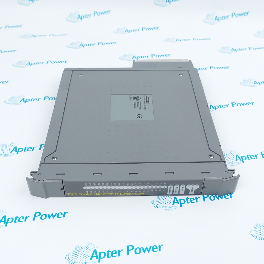
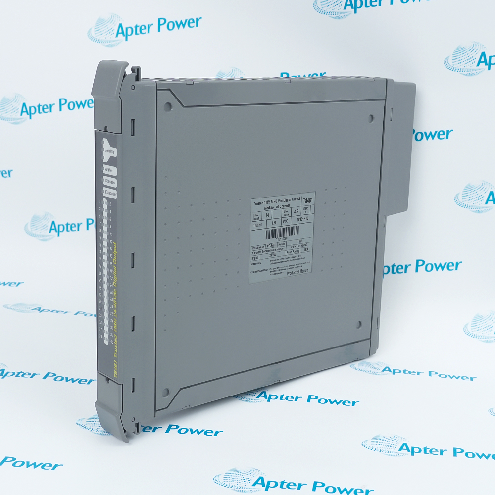
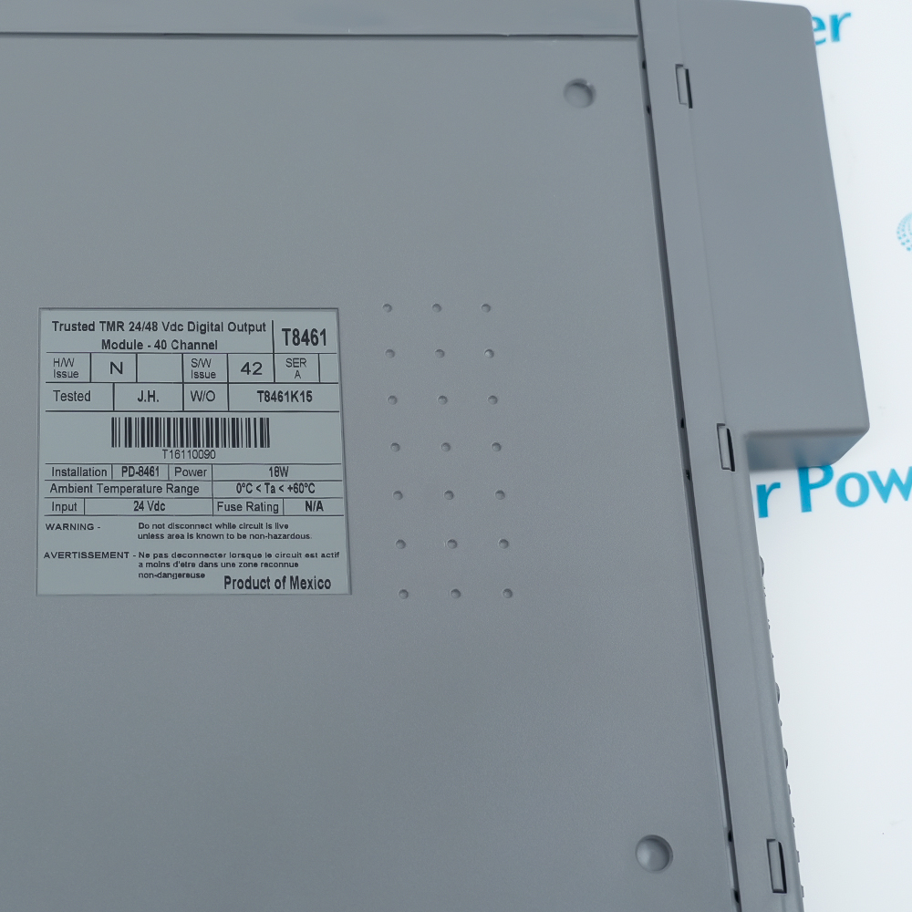
The T8461 is an ICS Triplex Trusted TMR 24/48 Vdc Digital Output Module for the Trusted 8000 system.
- Trusted TMR 24/48 Vdc Digital Output Module
- 40 monitored output channels
- 18–58 Vdc discrete output range
- Triplicated command processing and per-channel diagnostics
It drives forty monitored 24/48 Vdc loads with triplicated command processing and per-channel diagnostics. It handles discrete 18–58 Vdc outputs, measured current and voltage status, and line-fault data and operates with T8100 or T8300 chassis, matching field termination, Trusted TMR processor and TOOLSET configuration. Verify the exact hardware revision, matched termination and controlled application records before commissioning.
Important Notice: Use the complete T8461 code and verify the physical nameplate, current ICS Triplex / Rockwell Automation documentation, field wiring, project, and compatible system hardware before installation or replacement.
Apter Power T8461 Manuals and Guides
Important Notice: These are two separate Apter Power documents prepared from the official ICS Triplex source named in each document. Confirm the physical nameplate, current Rockwell Automation documentation, and applicable installation instructions before installation or replacement.
Shutdown solenoids
Uses the T8461 trusted tmr 24/48 vdc digital output module in a model-appropriate Trusted 8000 control or protection function.
Trip relays
Handles system status and diagnostics under the official engineering limits.
Fire and gas outputs
Uses the T8461 trusted tmr 24/48 vdc digital output module in a model-appropriate Trusted 8000 control or protection function.
Turbine auxiliary trips
Handles system status and diagnostics under the official engineering limits.
Read Rockwell Automation ICSTT-RM451D-EN-P and the applicable system installation instructions before use. Verify the physical nameplate, revision, slot and matched termination hardware.
1
Verify the exact model, hardware revision, firmware and nameplate before substitution.
2
Install only with T8100 or T8300 chassis, matching field termination, Trusted TMR processor and TOOLSET configuration; do not mix unmatched termination or base hardware.
3
De-energize or follow the approved live-insertion procedure and site safety plan before removal.
4
Preserve module keying, slot assignment, wiring polarity, shields, grounding and field power limits.
5
Complete application download, diagnostics, proof testing and functional acceptance before return to service.