-
Match the complete marking
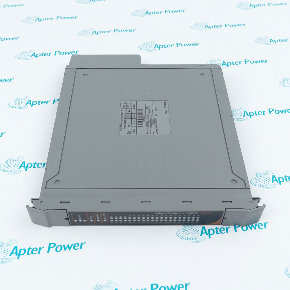
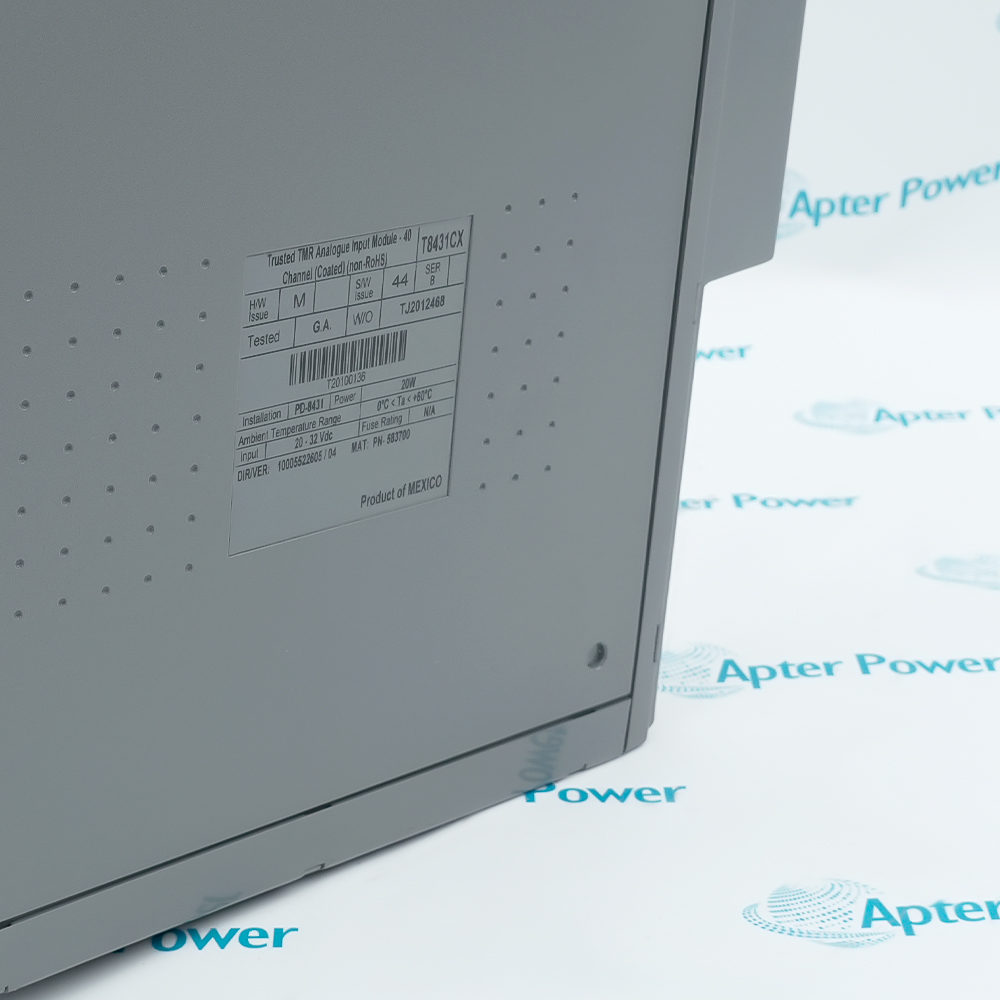
Provide the full T8431CX label, hardware and firmware revision, chassis slot and termination reference. Keep the CX variant identifiable.
-
Check the offered item before ordering
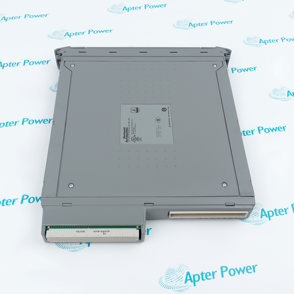
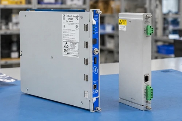
Request label and connector photographs. Have your maintenance team compare the offered T8431CX with the installed hardware and applicable Trusted configuration instructions.
Technical specifications for T8431CX
-
Manufacturer:ICS Triplex
-
Product Category:DCS Systems
-
Spare Part Number:T8431CX
-
Weight:1.15 kg
-
Tariff Code:8537101190
-
Analog inputs:40
-
Nominal signal:4–20 mA
-
Architecture:Triple modular redundant
-
Construction variant:Conformally coated; non-RoHS
-
Backplane voltage:20–32 V DC
-
Module power:20 W
-
Acquisition current range:0–22 mA
-
Measurement voltage range:0–5.5 V DC
-
Standard FTA shunt:250 Ω
-
Module input impedance:16.967 kΩ
-
Paired-module impedance:Half the individual module impedance
-
Channel-to-channel isolation:None
-
Conversion method:Sigma-delta; converter per channel per slice
-
Analog result selection:Median of three measurements
-
Analog count gradient:1024 counts per volt
-
Live-zero conversion:4 mA / 1 V = 0 counts
-
Full-scale conversion:20 mA / 5 V = 4096 counts
-
Open-circuit indication:−2048 analog counts
-
Current resolution:3.906 µA
-
Safety accuracy:±200 µA
-
Calibration accuracy:±0.15%
-
Threshold configuration:Four user thresholds with rising/falling hysteresis
-
Field channel numbering:1–40; 0 and 41 are internal references
-
Line-fault variable:Majority-voted Boolean
-
Discrepancy map:Three integer words: 1–16, 17–32, 33–40
-
SOE resolution:1 ms
-
Timestamp accuracy:±10 ms
-
Operating temperature:0 to +60 °C
-
Storage temperature:−25 to +70 °C
-
Relative humidity:10–95%, non-condensing
Information
- ICS Triplex T8431CX provides separate analog values, threshold states and wiring-fault indications. This separation lets the application evaluate whether a measurement is usable before applying process alarms or protective decisions.
State interpretation: Rising and falling thresholds provide hysteresis around configured input bands.
Fault discrimination: Wiring faults and internal channel discrepancies are available separately from the process value.
The reported analog count includes an offset chosen for 4–20 mA scaling. One volt corresponds to zero counts and five volts to 4096 counts. State and line-fault variables must be interpreted alongside this measurement: a numerical zero can represent a valid live-zero signal, while a separate negative sentinel identifies an open circuit.
Each channel can have independently configured line monitoring and state thresholds. Separate rising and falling thresholds prevent a noisy value from repeatedly crossing one ideal boundary. Sequence-of-events logging records configured state transitions; it is not a substitute for continuous analog trending or proof that the entire process response occurs at the event-clock resolution.
T8431CX Official Analog Input Manual Excerpt
Original English T8431 architecture, input conversion, threshold handling, diagnostics, indicators and electrical ratings. PDF · 10 pages.T8431CX Installation & Verification Guide
Apter Power field-verification workbook for loop burden, current injection, threshold tests, diagnostic mapping and controlled replacement. PDF · 5 pages.
Application scope: Applications should distinguish analog measurements, threshold bands and diagnostic validity. Safety functions depend on the approved controller, module revision, application and complete field circuit.
Triplicated transmitter acquisition
Acquire compatible sourcing 4–20 mA transmitters through a current-sinking input and the selected termination resistor.Threshold-based event recording
Record transitions between configured input bands while retaining separate analog values for process analysis.Field-circuit fault monitoring
Use channel line-fault and discrepancy variables to separate wiring defects from internal acquisition disagreement.Configured module replacement
Use an approved Companion Slot or SmartSlot arrangement to coordinate an active and standby module during maintenance.
Confirm transmitter supply, termination resistance, cable returns and channel identity before testing.
Review common references and external barriers where the field design requires them.
Keep the analog offset, conversion table and special fault values consistent with the application.
Verify rising and falling transitions separately instead of checking only one alarm point.
Match the approved hardware, firmware and spare-slot configuration before a changeover.
Confirm diagnostic health and end-to-end process scaling before restoring the channel to normal service.
Alternative Names
Technical notes
Loop burden: A 250 Ω termination resistor drops 5 V at 20 mA. Include transmitter operating voltage, cable resistance and other series elements when assessing supply compliance.
Live zero is not no current: An analog count of zero corresponds to 4 mA in the standard conversion. Do not interpret it as an open loop or zero physical current.
Hysteresis history: The same input near a threshold may produce different states depending on whether it is rising or falling. Preserve both thresholds when comparing test results.
Diagnostic mapping: The final discrepancy word contains channels 33–40, not sixteen additional field channels. Mask and label its bits according to the actual channel map.

FAQ View All FAQ
-
How should 2048 analog counts from T8431CX be converted to loop current?For the standard 250 Ω termination, voltage is counts/1024 + 1. Thus 2048 counts means 3 V and 12 mA. Apply this conversion to the analog rack, then check the corresponding state and line-fault variables before accepting the result.
-
Why does zero analog count on T8431CX not identify an open wire?Zero counts represents the valid 4 mA live-zero point. The defined open-circuit analog indication is −2048. Use the channel state and line-fault input to distinguish a circuit failure from a valid low-end process measurement.
-
Can two tests at the same current produce different T8431CX threshold states?Yes, within a hysteresis band the result depends on the previous state and whether the input approached from above or below. Test both directions and compare the configured rising and falling thresholds rather than changing scaling to force agreement.
-
What can state 7 on T8431CX mean when the field transmitter still produces a plausible current?It is an unknown state. Causes include insufficient valid slice measurements, a detected two-out-of-three discrepancy, or a simulated/uncommunicative module. Check slice health and communication as well as the external loop; a plausible transmitter current alone does not validate the returned measurement.
-
How does adding a partner module affect the input impedance seen by a T8431CX circuit?The effective module input impedance is halved when partner modules are fitted. Review the complete termination and source arrangement for the active/standby configuration instead of applying the individual module impedance to the pair.
-
Why might a T8431CX channel LED differ from a familiar alarm-color convention?Input LED modes are configurable for the threshold bands. Compare the installed configuration and numeric state with the front-panel indication before diagnosing the circuit solely from LED color.
-
Can an SOE entry from T8431CX replace an analog trend during a slow process drift?No. SOE records configured changes of state, while a signal can drift within one band without such a transition. Retain analog trending where the shape or rate of the measurement matters, and interpret event times separately from analog sampling.
-
What should be checked if many T8431CX channels appear abnormal after one chassis feed fails?Inspect module Healthy indications and both chassis feeds before replacing transmitters. A flashing red Healthy indicator can accompany loss of one 24 V chassis feed. Compare channel diagnostics and the remaining supply condition under the approved maintenance procedure.
Supporting new and legacy automation
-
Please try to be as accurate as possible with your search.
-
We can quote you on 1000s of specialist parts, even if they are not listed on our website.
-
We can't find any results for “”.
Related cases and sourcing guidance
View all case studiesYou May Also Like
Product Browsing History
-
Whatsapp: +86 18030235313
Send us a message. -
sales13@apterpower.com
Complete our online form. -
+86 18030235313
Speak to our team in your native language.