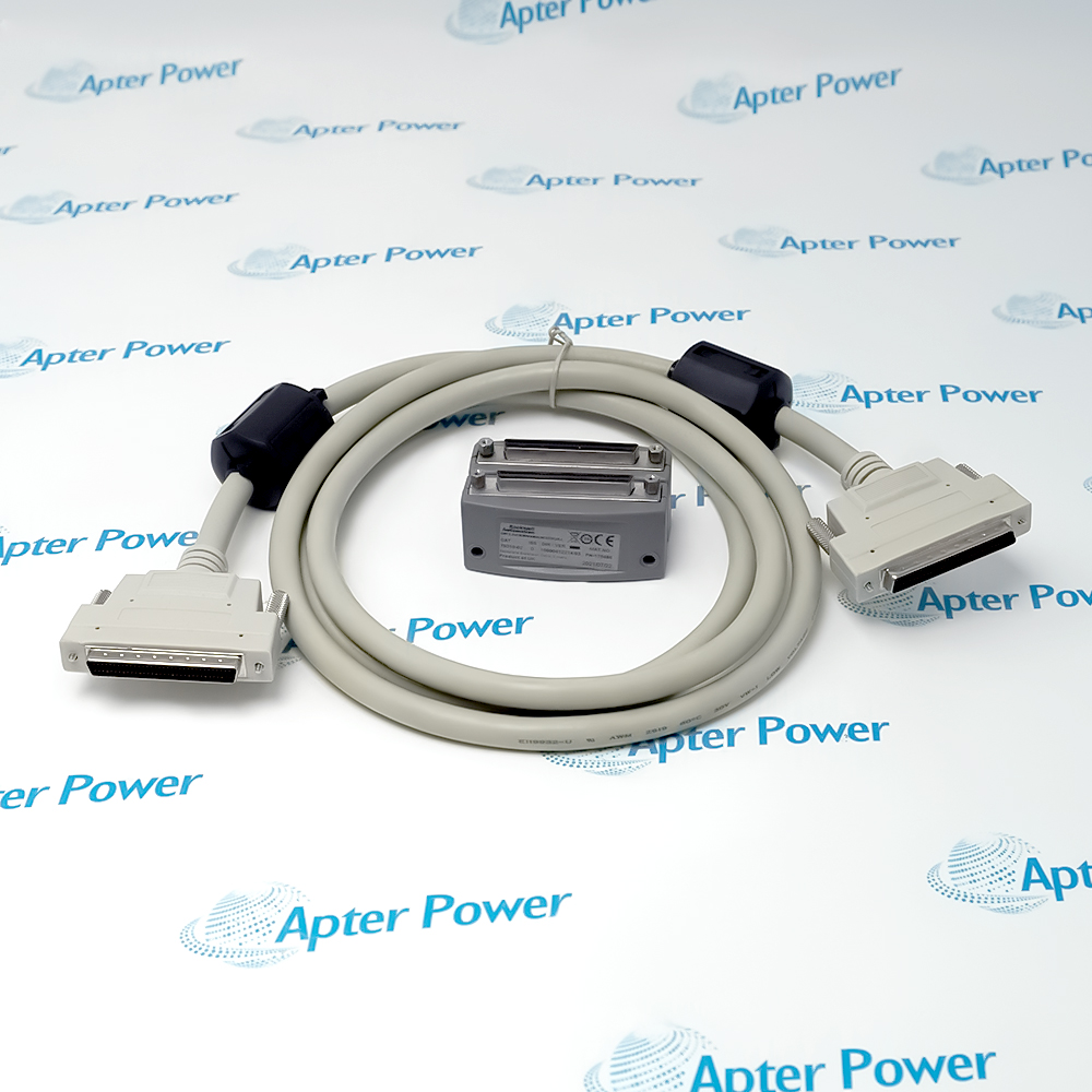
-
Match the complete marking
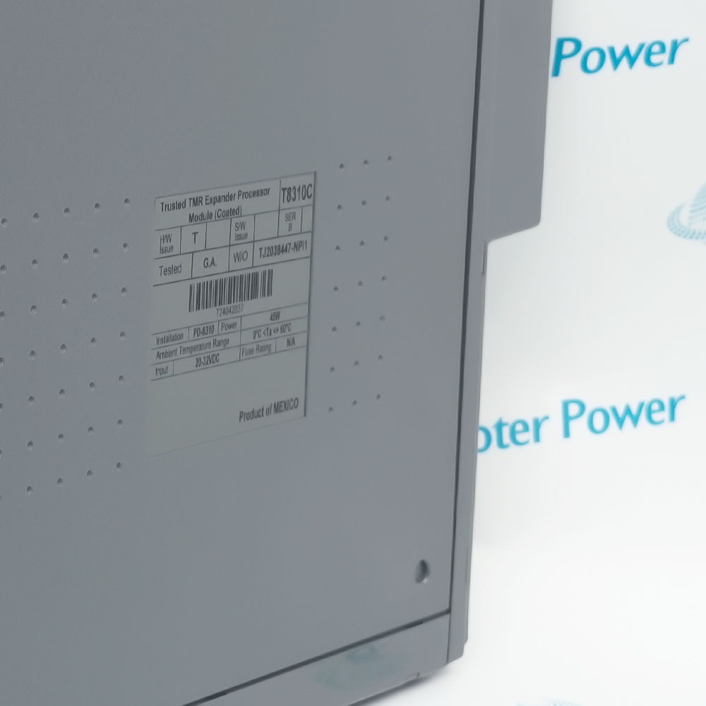
Provide the T8310C label, hardware series, revision and expander chassis address. Identify the active or standby processor slot.
-
Check the offered item before ordering
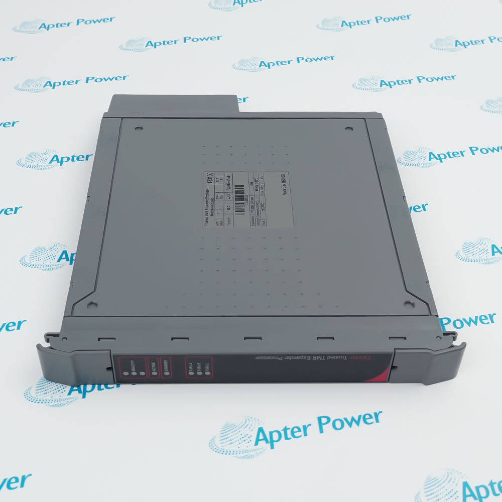
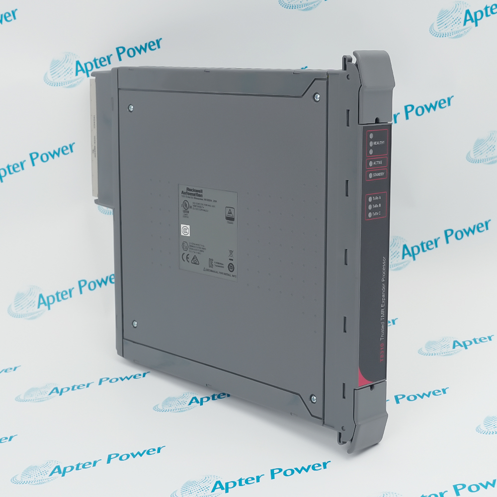
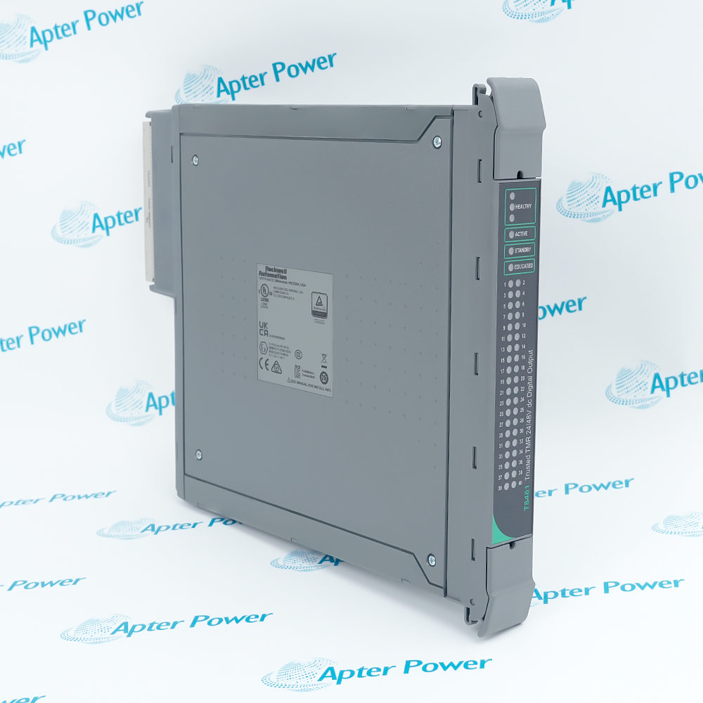
Request module and connector photographs. Have your maintenance team compare the offered T8310C with the installed chassis and applicable Trusted expansion instructions.
Technical specifications for T8310C
-
Manufacturer:ICS Triplex
-
Product Category:DCS Systems
-
Spare Part Number:T8310C
-
Weight:1.28 kg
-
Tariff Code:8537101190
-
Module function:Expander-side bus processor
-
Redundancy architecture:Hardware-implemented TMR, lock-step
-
Operating degradation:3–2–0
-
Primary fault-containment regions:3: A, B and C
-
Additional monitoring region:FCR D
-
Backplane supply range:20–32 V DC
-
Supply arrangement:Dual redundant nominal 24 V DC chassis feeds
-
Power, Series A/B:45 W
-
Power, Series C:20 W
-
Physical module positions:T8300 processor slots PL1 or PL2
-
Toolset slot numbers:13 or 14
-
Toolset chassis range:2–15
-
Expander Bus topology:Triplicated point-to-point
-
Copper link type:Unshielded twisted pair through approved TC-301 assembly
-
Maximum copper distance:30 m using TC-301
-
Maximum optical distance:10 km using T8314 fiber TX/RX units
-
Expander Bus data rate:1.5 Gbit/s
-
IMB data rate:Up to 12.5 Mbit/s
-
IMB clock rate:12.5 million symbols/s
-
IMB data width:8 bits, bidirectional
-
Chassis identification:4-bit code
-
IMB power channels:3 independent diode-coupled supplies
-
Receive activity indication:Green
-
Transmit activity indication:Red; absent during standby
-
Operating temperature:0 to +60 °C
-
Storage temperature:−25 to +70 °C
-
Relative humidity:10–95%, non-condensing
-
Internal fusing:Not user serviceable
Information
- ICS Triplex T8310C preserves the controller-to-I/O communication path across an expanded chassis installation. Its message voting can mask a single link fault during operation, making link-quality diagnostics important even when process data continues to arrive.
Fault localization: Isolated containment regions limit propagation between communication and processing paths.
Service coordination: Active and standby processors share a defined chassis arrangement for controlled changeover.
Three primary fault-containment regions handle the triplicated communication paths, power supplies and control logic. Received traffic is resynchronized and voted before forwarding. A separate monitoring region supports non-critical display functions. Continued communication after one fault therefore does not mean that all physical paths remain healthy; error counters and slice status provide the necessary distinction.
Both active and standby units generate independent IMB power supplies, while the active processor provides synchronized IMB clocks and forwards system watchdog and power-fail signals. The chassis address and I/O connection-table entry remain part of the system configuration even though the module itself requires no local setup. A successful replacement must restore communication, diagnostics and the intended redundancy state.
T8310C Official Expander Processor Manual Excerpt
Original English T8310 bus architecture, installation positions, configuration and indicators, plus the safety-manual mapping of the coated T8310C variant. PDF · 10 pages.T8310C Installation & Verification Guide
Apter Power service workbook for chassis identity, link routing, dual supplies, active/standby behavior and post-maintenance verification. PDF · 5 pages.
Application scope: Use the module within the supported Trusted system topology and revision combination. Its interference-free communication role can form part of the validated safety communication path; it is not an independent safety logic solver.
Additional I/O chassis
Extend controller access to the configured I/O modules on a Trusted Expander Chassis.Copper chassis links
Use the approved TC-301 adapter and cable arrangement within the copper-distance limit.Remote optical extension
Use compatible T8314 optical equipment and the corresponding TC-302/TC-303 connections for supported remote arrangements.Redundant expansion service
Coordinate active and standby expander processors while monitoring individual link health and chassis supplies.
Install only in PL1 or PL2; an ordinary I/O position is unsuitable and can damage the module.
Apply the series-specific power rating and retain the complete coated-module identity.
Retain command/response routing and adapter connections; do not substitute ordinary Ethernet equipment.
Check the two chassis feeds and diagnostic readings before attributing multiple symptoms to one processor.
Confirm the replacement’s Healthy indications and the approved transfer procedure before removing the original.
Review per-link errors and redundancy status even when the controller still exchanges I/O data.
Alternative Names
Technical notes
Two different meanings of C: The catalog suffix C denotes conformal coating. Hardware Series C is a separate label and has a different power rating from Series A/B; identify both before a power-budget review.
Masking is not repair: Voting can preserve communication after a link fault. Treat persistent error counts or slice faults as maintenance evidence even if the current process values remain plausible.
Slot numbering: PL1/PL2 are the physical processor positions; the toolset addresses them as slots 13/14. Mixing physical labels with I/O-slot numbers can misdirect configuration checks.
Standby activity: A standby module does not show red transmit activity. Evaluate the Healthy and Standby indications together before interpreting absent transmit indication as a failed link.

FAQ View All FAQ
-
Does the C suffix on T8310C establish which power rating applies?No. It identifies conformal coating. Read the separate hardware-series marking: the power rating is 45 W for Series A/B and 20 W for Series C. Use the actual unit series when reviewing the chassis power and thermal budget.
-
Why can T8310C keep transferring data while one link reports errors?The triplicated paths resynchronize and vote received data, allowing a single-path fault to be masked. Review error counts and slice status instead of treating continued I/O traffic as proof that every path is healthy.
-
Can T8310C be installed in a free ordinary I/O slot?No. It belongs only in the two expander-processor positions, PL1 or PL2. Confirm the physical position before insertion; the toolset represents these positions as slots 13 and 14.
-
Does using UTP cable make T8310C compatible with an ordinary Ethernet switch?No. UTP identifies the cable medium, not Ethernet protocol compatibility. Retain the approved triplicated Expander Bus connection through its designated adapter and cable assemblies.
-
Why may the standby T8310C show receive activity without transmit activity?Standby operation has no red transmit indication. Compare the Standby and Healthy indications and the system status before diagnosing this expected absence as a transmitter failure.
-
What configuration is still needed when T8310C requires no local module setup?The chassis address and module entry in the I/O connection table still have to match the installation. Verify the chassis number, processor-slot number and application access to status information.
-
Can a single healthy T8310C establish the safety integrity of the complete installation?No. The expander serves the communication path rather than acting as a standalone safety logic solver. The approved controller, I/O, field circuits, application and safety communication configuration determine the complete function.
-
What should be checked after changing over to a replacement T8310C?Check the intended active/standby state, all Healthy indications, both chassis supplies and per-link diagnostics. Then verify affected I/O communication and the required process response before releasing maintenance controls.
Supporting new and legacy automation
-
Please try to be as accurate as possible with your search.
-
We can quote you on 1000s of specialist parts, even if they are not listed on our website.
-
We can't find any results for “”.
Related cases and sourcing guidance
View all case studiesYou May Also Like
Product Browsing History
-
Whatsapp: +86 18030235313
Send us a message. -
sales13@apterpower.com
Complete our online form. -
+86 18030235313
Speak to our team in your native language.