Speak to a sourcing specialist
sales13@apterpower.com

IC693MDL741G

12/24 VDC 16-Point Negative Logic Output Module
In Stock
Ships by Friday, November 6
Fast Shipping Available
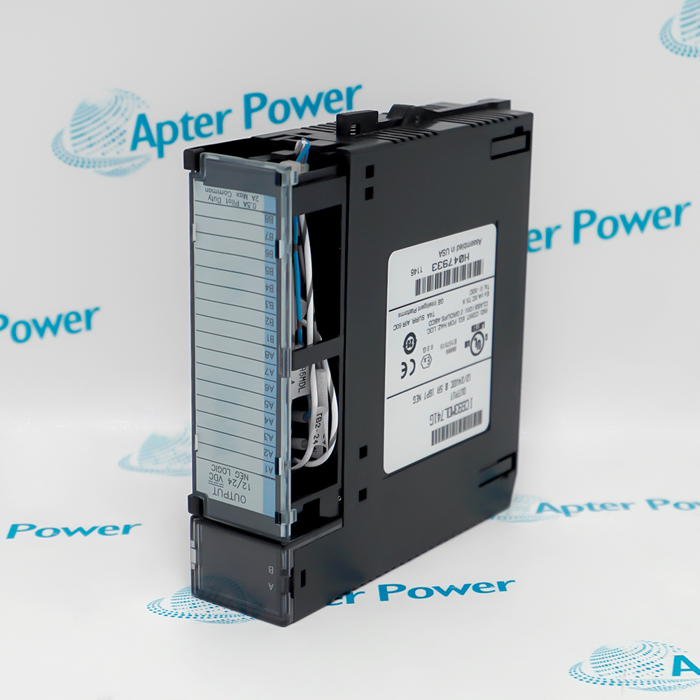
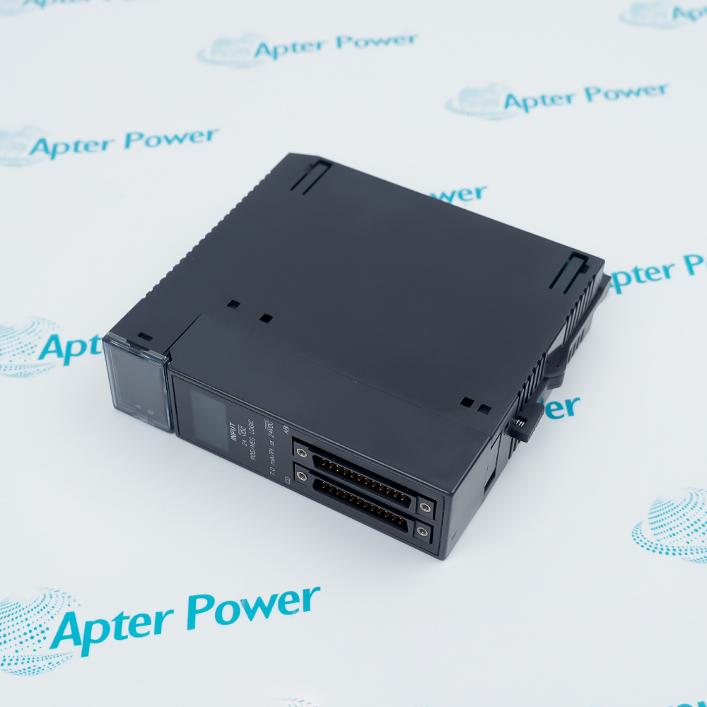
General Electric IC693MDL741G, angled front view of black module with grey terminal cover and terminal labels
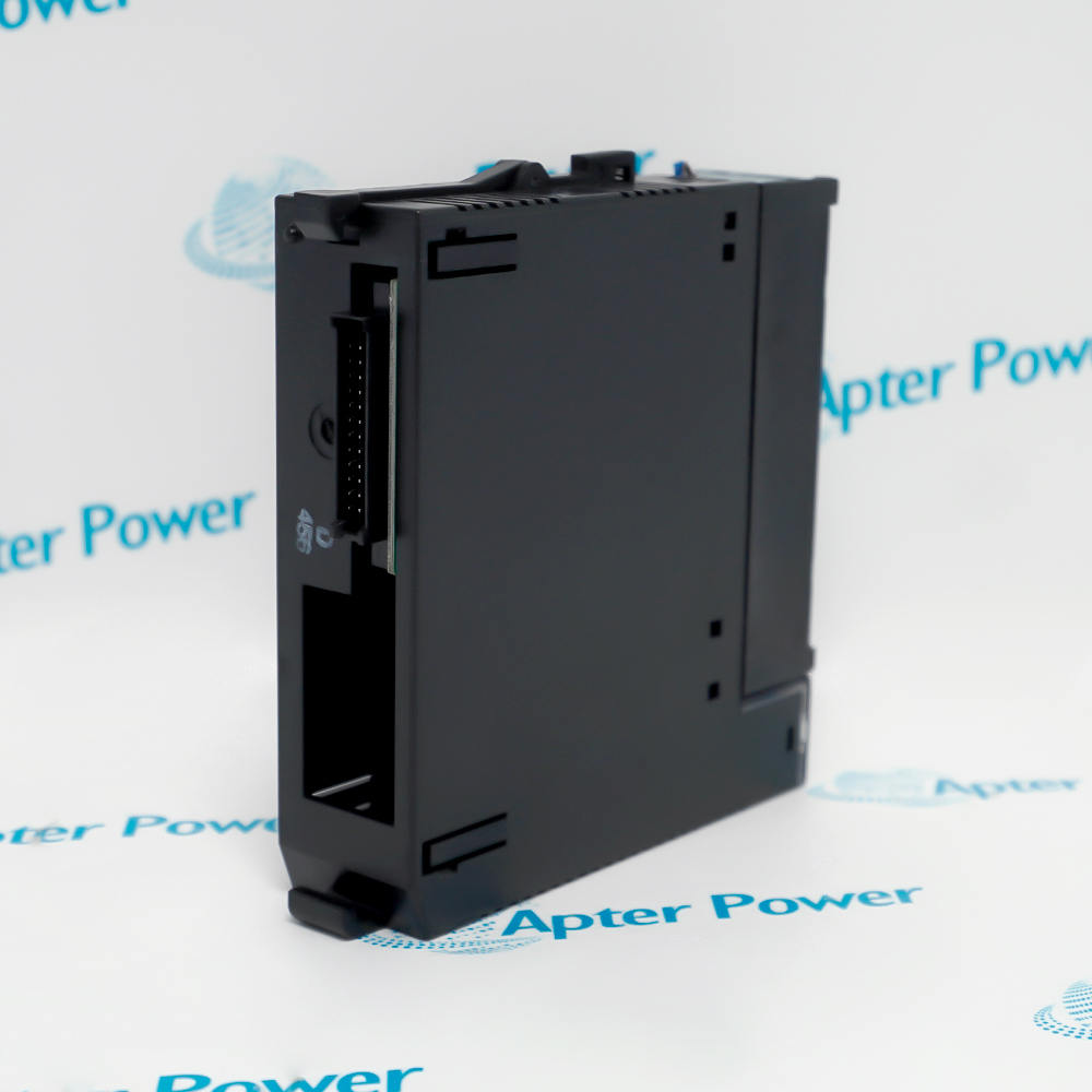
General Electric IC693MDL741G, angled side view of black housing with open bus connector slot
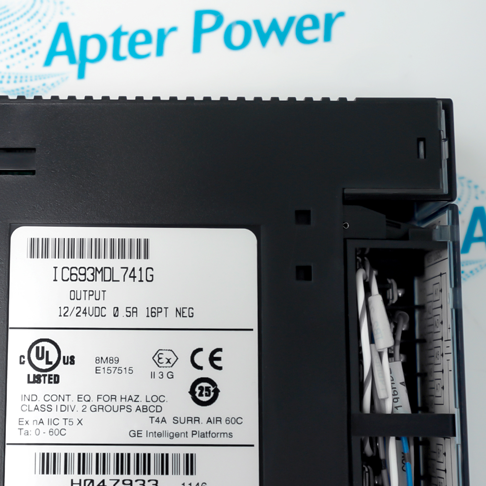
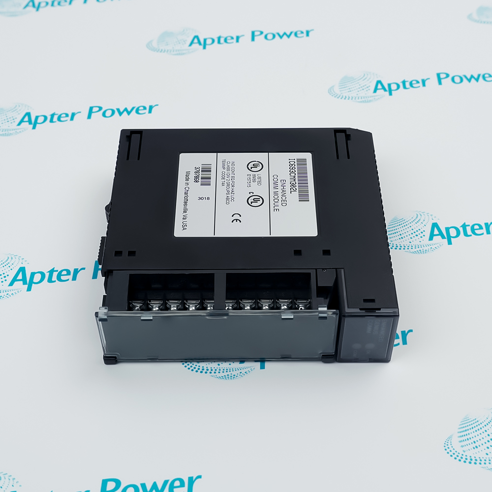
General Electric IC693MDL741G, close-up of label showing output 12/24VDC 0.5A 16PT NEG and approvals
General Electric IC693MDL741G, angled front view of black module with grey terminal cover and terminal labels
General Electric IC693MDL741G, angled side view of black housing with open bus connector slot
General Electric IC693MDL741G, close-up of label showing output 12/24VDC 0.5A 16PT NEG and approvals
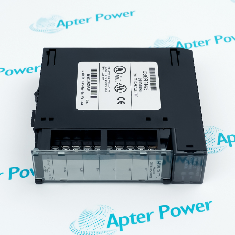
Product image is representative; revision or series may vary. Contact us to request a specific version.

Product Describe:

GE IC693MDL741G is a 16-point 12/24 VDC negative-logic output module for the Series 90-30 PLC. It switches two groups of eight field outputs from the configured PLC output table.
Get a quick price for IC693MDL741G
E-mail *
Mobile *
Company
Content *
Quantity *
Upload (gif, jpg, jpeg, png, bmp, doc, docx, xls, xlsx, ppt, pdf, csv)
For more information on how your data is processed and stored by Apterpower please read our privacy policy

What happens after you enquire

  • 1

    Requirement review

    We review the part number, quantity and delivery requirements and ask for any missing details.
  • 2

    Quotation and availability

    We confirm the proposed item, condition, availability, price and estimated lead time in the quotation.
  • 3

    Order confirmation and dispatch

    Once the quotation and purchasing details are agreed, your contact will coordinate the order and available dispatch information.

Technical specifications for IC693MDL741G

  • Manufacturer:
    General Electric
  • Product Category:
    PLC Systems
  • Spare Part Number:
    IC693MDL741G
  • Estimated shipping dimensions:
    3.5x13x13.5cm
  • Weight:
    0.28 kg
  • Tariff Code:
    8537101190
  • Counliy of origin:
    USA
  • Output points:
    16
  • Output grouping:
    2 groups of 8
  • Logic type:
    Negative logic
  • Output voltage:
    12 to 24 VDC, +20/-15 percent
  • Current per point:
    0.5 A maximum
  • Current per common:
    2 A maximum
  • Output voltage drop:
    0.5 V maximum
  • Off-state leakage:
    1 mA maximum
  • On/off response:
    2 ms maximum
  • Field-to-logic isolation:
    1500 V
  • Group-to-group isolation:
    500 V
  • Backplane current:
    110 mA at 5 VDC
  • Output fuses:
    None
  • Hardware revision:
    G

Information

Overview Manuals Common Applications Product Precautions
IC693MDL741G provides sixteen negative-logic DC output points for a configured Series 90-30 PLC station.
  • Switches sixteen negative-logic DC field outputs
  • Separates the points into two independently wired groups
  • Uses the Series 90-30 backplane for logic and module control
  • Provides front status indication for output commands

The module occupies an I/O slot in a Series 90-30 baseplate and uses a user-supplied field source. Commissioning covers slot configuration, two-group commons, load wiring, output-table mapping, current limits and controlled actuation tests.

Important Notice: Confirm IC693MDL741G, Series 90-30 baseplate and CPU, revision G, I/O slot, two eight-point groups, 12/24 VDC field source, negative-logic wiring, load currents, commons, grounding, output map and controlled actuation-test results before commissioning.

Apter Power IC693MDL741G Manuals and Guides

The first document is the model-specific technical and system reference. The second is a distinct field workbook for installation, wiring, commissioning and acceptance records.


Series 90-30 actuator control
Commands documented relays, solenoids or indicators from the PLC.
Two-group output marshalling
Separates field loads across the module's two common groups.
Machine-control panel service
Restores a documented sixteen-point negative-logic output position.
Output interlock verification
Supports controlled command and field-response checks after maintenance.
Read the applicable GE installation instructions before work. Verify IC693MDL741G, the installed host system and all configured field interfaces before isolation, wiring or commissioning.
1
Confirm IC693MDL741G and hardware revision G on the module label.
2
Place all connected loads in a safe state and isolate field power.
3
Record both commons and every output point before disconnecting wiring.
4
Verify negative-logic polarity and the external 12/24 VDC source.
5
Inspect terminal-block keying, baseplate connector and conductor condition.
6
Restore the documented Series 90-30 slot and output mapping.
7
Check backplane and module diagnostics before enabling field power.
8
Command each output under controlled conditions and verify load response.

Technical notes

Install IC693MDL741G in an approved Series 90-30 I/O slot and isolate the external 12/24 VDC load supply before handling the terminal block. Preserve both eight-point commons and verify output polarity, load current, interlocks and every commanded field response.

FAQ View All FAQ

  • What identity details must be checked before IC693MDL741G is removed?
    Confirm IC693MDL741G, Series 90-30 baseplate and CPU, revision G, I/O slot, two eight-point groups, 12/24 VDC field source, negative-logic wiring, load currents, commons, grounding, output map and controlled actuation-test results before commissioning.
  • How does IC693MDL741G perform its documented 12/24 vdc 16-point negative logic output module role?
    Switches sixteen negative-logic DC field outputs. It switches two groups of eight field outputs from the configured PLC output table.
  • Which GE Series 90-30 PLC interfaces must be recorded for IC693MDL741G?
    The module occupies an I/O slot in a Series 90-30 baseplate and uses a user-supplied field source. Commissioning covers slot configuration, two-group commons, load wiring, output-table mapping, current limits and controlled actuation tests.
  • What isolation and ESD controls apply while handling IC693MDL741G?
    Place all connected loads in a safe state and isolate field power. Record both commons and every output point before disconnecting wiring.
  • How should the installed configuration be restored after fitting IC693MDL741G?
    Restore the documented Series 90-30 slot and output mapping.
  • Which diagnostic evidence confirms that IC693MDL741G is recognized correctly?
    Check backplane and module diagnostics before enabling field power.
  • What replacement records should be retained for IC693MDL741G?
    Confirm IC693MDL741G and hardware revision G on the module label. Inspect terminal-block keying, baseplate connector and conductor condition.
  • What final acceptance test is required before IC693MDL741G returns to service?
    Command each output under controlled conditions and verify load response.
Related reading

Related cases and sourcing guidance

View all case studies
SPEAK TO OUR TEAM
Let’s find the right solution for you.
Send us the part number, quantity and delivery destination. Our team will help confirm availability and lead time.
  • Whatsapp: +86 18030235313

    Send us a message.
  • sales13@apterpower.com

    Complete our online form.
  • +86 18030235313

    Speak to our team in your native language.