Speak to a sourcing specialist
sales13@apterpower.com

G128-0001

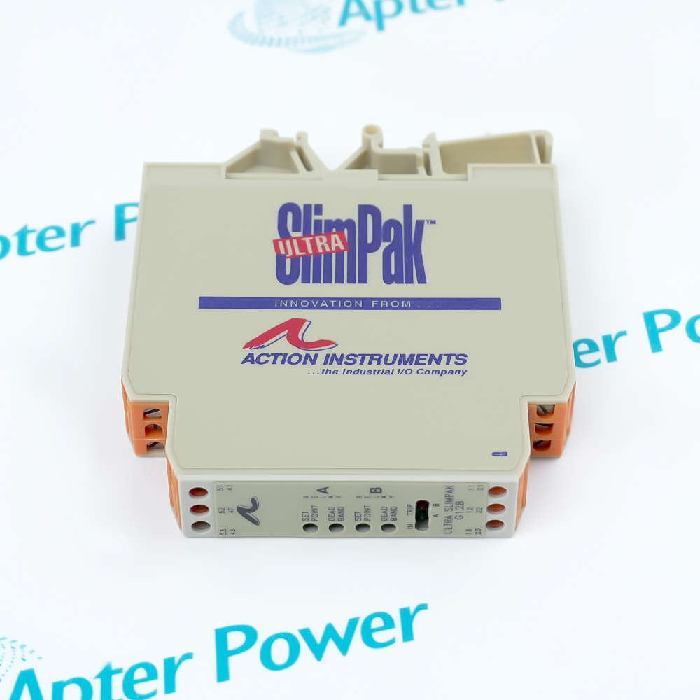
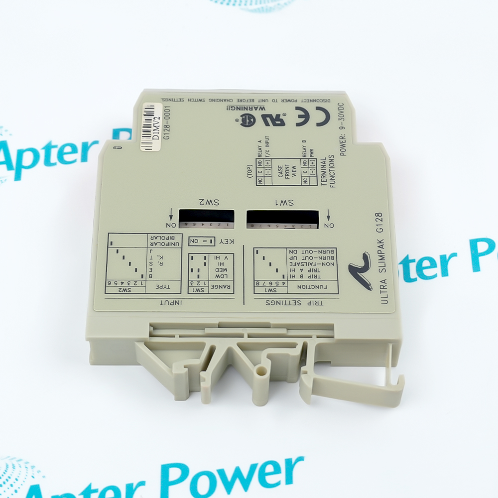
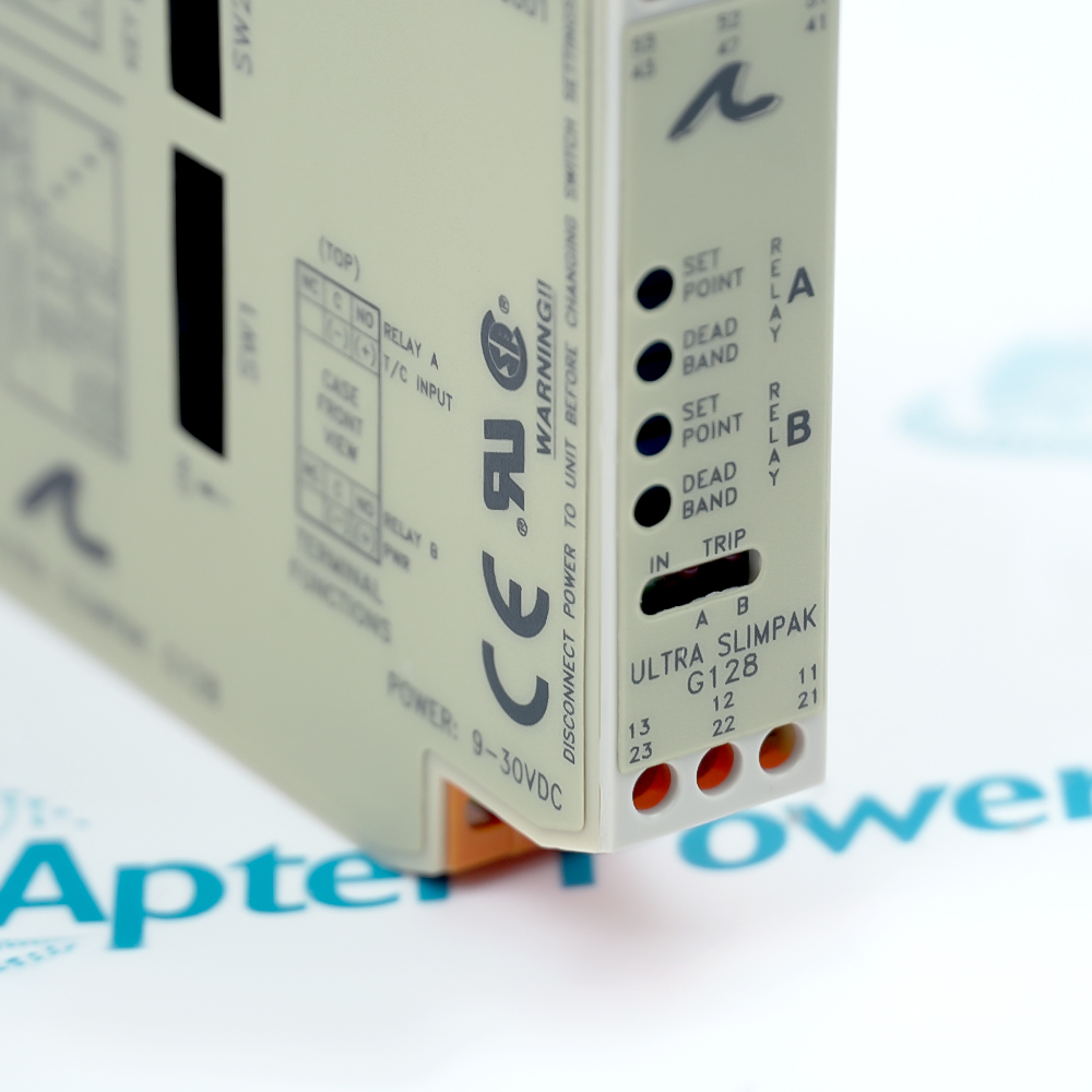
Eurotherm G128-0001 Ultra SlimPak Thermocouple Input Limit Alarm
Action Instruments G128-0001 (1)
Action Instruments G128-0001 (2)
Action Instruments G128-0001 (3)
Action Instruments G128-0001 (1)
Action Instruments G128-0001 (2)
Action Instruments G128-0001 (3)
Product image is representative; revision or series may vary. Contact us to request a specific version.

Product Describe:

Eurotherm G128-0001 is a DIN-rail thermocouple input limit alarm with two configurable setpoints, two independent relay outputs and input-terminal cold-junction compensation.
  • Manufacturer part number
    G128-0001
  • Shipping
    Swift global dispatch
  • Condition
    New, original product
  • Shipping size (est.)
    9.0cm x 11.02cm x 1.75cm
  • Country of Origin
    USA
Get a quick price for G128-0001
E-mail *
Mobile
Company
Content *
Quantity *
Upload (gif, jpg, jpeg, png, bmp, doc, docx, xls, xlsx, ppt, pdf, csv)
For more information on how your data is processed and stored by Apterpower please read our privacy policy

What happens after you enquire

  • 0

    Review your reference

    Send the complete G128-0001 marking, installed thermocouple type, required alarm thresholds and available label photos so the required configuration can be identified.

  • 1

    Confirm the offer

    Compare the offered module, switch positions and included DIN-rail or power accessories with the written quotation before approving the alarm-circuit replacement.

  • 2

    Arrange dispatch

    Confirm the receiving address and required handling, then obtain the dispatch and tracking details for the G128-0001 shipment.

  • Match the complete marking

    Include G128-0001 and every visible revision or calibration marking on the item. Keep the same reference on your enquiry and quotation.

  • Check the offered item before ordering

    Request available label, terminal and switch photos. Have your maintenance team compare the offered G128-0001 with the installed thermocouple circuit, relay wiring and applicable Eurotherm documentation.

Technical specifications for G128-0001

  • Manufacturer:
    Eurotherm
  • Product Category:
    General Automation
  • Spare Part Number:
    G128-0001
  • Weight:
    0.254 kg
  • Input sensor:
    Thermocouple; selectable B, E, J, K, R, S or T
  • Cold-junction compensation:
    At thermocouple input terminals
  • Input impedance:
    >1 MΩ
  • Input bias current:
    <1.5 µA for burnout detection
  • Differential overvoltage:
    ±10 V
  • Common-mode input-to-ground limit:
    1800 V DC maximum
  • Input terminals:
    41 positive; 42 negative
  • Setpoint channels:
    Two independent; HI or LO per channel
  • Setpoint adjustability:
    Across 100% of selected input span
  • Static deadband:
    0.25–5% of selected span per setpoint
  • Dynamic trip qualification:
    100 ms uninterrupted condition
  • Normal analog response:
    <250 ms, 10–90%
  • Relay arrangement:
    Two SPDT Form C; one per setpoint
  • Relay A terminals:
    52 common; 51 NO; 53 NC
  • Relay B terminals:
    12 common; 11 NO; 13 NC
  • Resistive contact rating:
    5 A at 120 V AC or 28 V DC; 2 A at 240 V AC
  • DC supply:
    9–30 V DC, inverter isolated
  • DC supply terminals:
    21 positive; 22 negative
  • Power consumption:
    1.5 W typical; 2.5 W maximum
  • Input-range LED:
    Green; >110% flashes 8 Hz, <-10% flashes 4 Hz
  • Trip indication:
    Red LED per setpoint; lit when tripped
  • Common-mode rejection:
    120 dB, DC–60 Hz
  • Circuit isolation:
    1800 V DC between contacts, input and power
  • Wire termination:
    Screw, 12–22 AWG
  • DIN-rail mounting:
    TS32 or TS35
  • Operating ambient:
    0–55 °C on horizontal DIN rail
  • Storage ambient:
    −15 to +70 °C
  • Operating humidity:
    15–95% noncondensing at 45 °C

Information

Overview Downloads Applications / Compatibility Product Precautions
  • Eurotherm G128-0001 translates thermocouple temperature into two relay alarm decisions for an installed monitoring or control circuit.
Product role: Thermocouple input limit alarm
Trip architecture: Two independently configurable setpoints
Mounting: TS32 or TS35 DIN rail
The G128 receives a thermocouple signal through input-terminal cold-junction compensation. Field-selected input type and range convert that signal into a process value for two independent alarm comparisons; the module is a limit alarm rather than a temperature controller.

Each channel has its own HI or LO trip selection and adjustable deadband. The corresponding Form C relay can be arranged for failsafe or non-failsafe behavior, so the plant PLC or interlock must be checked against the actual switch positions and the required normal, alarm and power-loss states.

The module mounts on standard TS32 or TS35 DIN rail. Final threshold calibration is performed after thermal equilibrium in the installed cabinet. Compare the thermocouple type, input span, burnout direction and relay wiring with the existing instrument loop before energizing a replacement.
Controller platform reference: Ultra SlimPak G-series alarm platform. Match the installed thermocouple and relay logic.
Technical downloads for Eurotherm G128-0001: the original manufacturer data sheet and an Apter Power installation and commissioning guide.
The original Eurotherm data sheet is provided in full. The Apter Power guide focuses on installation checks and commissioning decisions; use the manufacturer procedures and local site controls during work.
Before installing G128-0001, compare its input, switch and relay wiring with the machine alarm drawing; isolate the instrument circuit.
Isolate before switch changes

Remove DC power before changing SW1 or SW2; live switch adjustment can damage the module.

Check thermocouple polarity

Land the positive and negative sensor leads on the specified input terminals and keep the input junction representative of the measured circuit.

Separate contact and supply wiring

Identify relay commons, NO/NC contacts and DC supply terminals before energizing; unused positions are not spare signal terminals.

Suppress inductive loads

Fit a correctly rated diode or MOV/RC network across the external load, close to the coil, to limit relay arcing and interference.

Manage rail heat

Check airflow in dense or vertical rail groups and keep the installed cabinet within the specified operating ambient.

Prove both thresholds

After final warm-up, inject a calibrated thermocouple signal and record trip, reset and power-loss contact states for channels A and B.

Alternative Names

Eurotherm G128-0001 Action Instruments G128-0001 Ultra SlimPak G128-0001

Technical notes

Signal relationship: The thermocouple input, terminal cold-junction compensation and selected range feed two independent threshold decisions; each decision controls one Form C relay.

Installation boundary: Switch settings and relay contact sense determine the actual alarm behavior. De-energize before switch changes and verify trip, reset and power-loss states after final calibration.

Technical reference: Eurotherm Ultra SlimPak G128-0001 Data Sheet, 721-0654-00-H. Input, switching, wiring and thermal ratings apply to the documented G128 design.


FAQ View All FAQ

  • How should G128-0001 relay contacts be interpreted by a PLC when failsafe mode is selected?
    Determine the energized normal state from the selected HI/LO and failsafe switches, then test COM–NO and COM–NC at normal input, alarm input and loss of DC power. Record the PLC input sense from those measured states; the contact label alone does not define the plant alarm logic.
  • What is the correct fault-isolation sequence if G128-0001 shows an input-range LED flash but no expected relay trip?
    First compare the thermocouple millivolts and polarity at the input terminals with the selected type and range. Then check burnout direction, HI/LO selection, setpoint and deadband before testing each relay contact. A flashing input LED identifies an out-of-range condition, not by itself a failed relay.
  • How can the thermocouple type and trip behavior of G128-0001 be changed without damaging the module?
    Remove DC power before changing SW1 or SW2. Use the data-sheet switch tables for the intended thermocouple type, range, trip direction, failsafe mode and burnout direction, then apply a calibrated thermocouple source and prove both trip and reset points.
  • Why might G128-0001 appear to chatter near a threshold even though its relay has a time-qualified trip?
    Check the actual sensor noise and cold-junction wiring, then measure the trip and reset temperatures separately. Set a suitable deadband for the process and verify that the input remains beyond the threshold long enough for the dynamic qualification; a mis-set threshold or noisy junction can still cause repeated transitions.
  • What acceptance check should follow relocation or replacement of G128-0001?
    Calibrate in the final installation after thermal equilibrium, using a traceable thermocouple millivolt source. Set deadband minimum while establishing each trip point, then adjust and prove the reset point. Record input type, range, switch positions and measured A/B relay states.
  • How should an inductive load connected to G128-0001 be protected?
    Place suppression directly across the load with short leads. The manufacturer shows a diode for a DC inductive load and a suitably rated MOV with RC snubber for AC service; select component ratings for the actual coil and verify contact current stays within the applicable resistive rating.
  • What must be checked if five or more G128-0001 modules are installed on a vertical DIN rail?
    Review rail orientation, spacing and enclosure heat removal. The manufacturer recommends circulating air or the HS01 heat sink for five or more vertically mounted modules; confirm the cabinet temperature remains within the module operating limit under full load.
  • Can the standard factory switch settings on G128-0001 be assumed to match a removed unit?
    No. The documented factory preset applies only unless another configuration was specified, and field switches or calibration may have changed. Compare the removed and offered switch positions, thermocouple type, selected range, A/B trip sense, burnout behavior and calibrated thresholds before interchange.
Manufacturers

You May Also Like

Explore related automation components available through Apter Power.
SPEAK TO OUR TEAM
Let’s find the right solution for you.
Send us the part number, quantity and delivery destination. Our team will help confirm availability and lead time.
  • Whatsapp: +86 18030235313

    Send us a message.
  • sales13@apterpower.com

    Complete our online form.
  • +86 18030235313

    Speak to our team in your native language.