Speak to a sourcing specialist
sales13@apterpower.com

991-06-70-03-05

Thrust Transmitter
Ships by Thursday, November 12
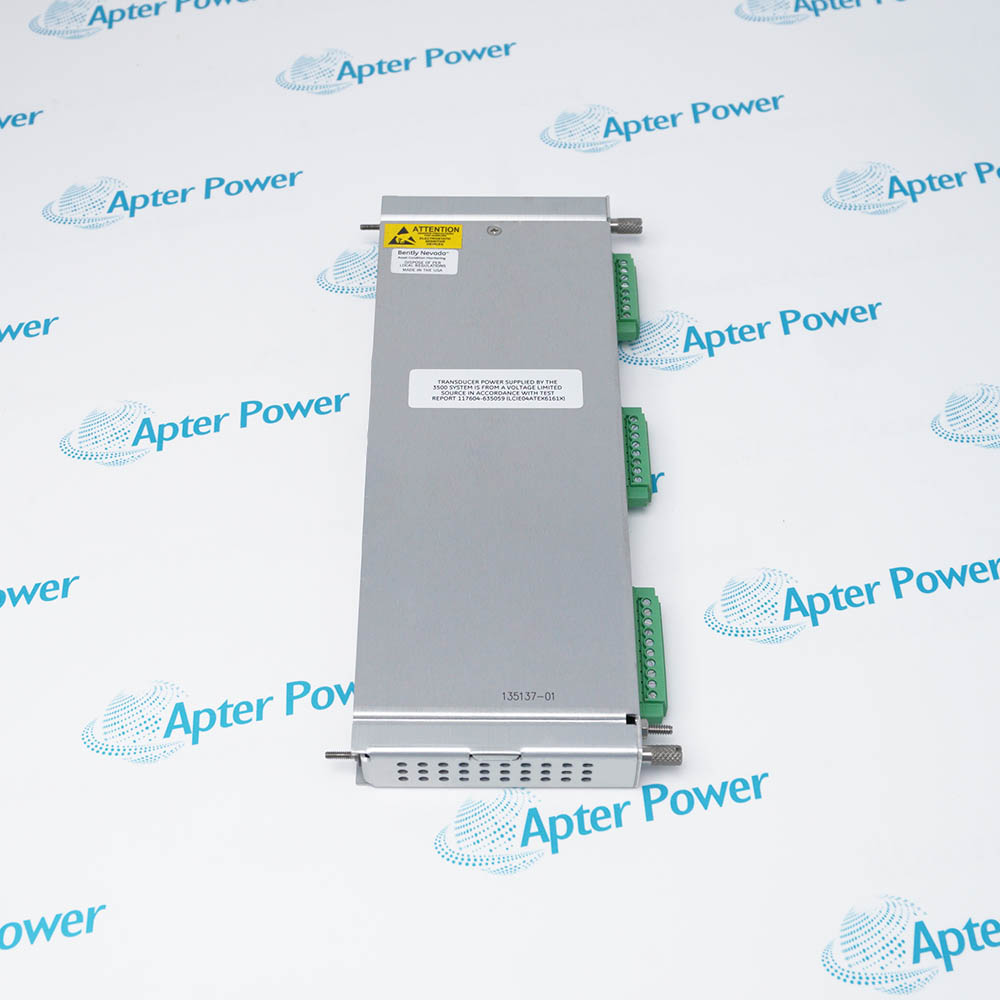
Product image is representative; revision or series may vary. Contact us to request a specific version.

Product Describe:

Bently Nevada 991-06-70-03-05 is a two-wire axial-position transmitter with a 0.6–0–0.6 mm range and a matched 7 m 3300 NSv transducer system. It provides a 4–20 mA signal to the receiving control system.
  • Manufacturer part number
    991-06-70-03-05
  • Shipping
    Swift global dispatch
  • Condition
    New, original product
  • Shipping size (est.)
    10cm x 7.4cm x 5.8cm
  • Country of Origin
    USA
Get a quick price for 991-06-70-03-05
E-mail *
Mobile *
Company
Content *
Quantity *
Upload (gif, jpg, jpeg, png, bmp, doc, docx, xls, xlsx, ppt, pdf, csv)
For more information on how your data is processed and stored by Apterpower please read our privacy policy

What happens after you enquire

  • 0

    Review your reference

    Send the complete Bently Nevada 991-06-70-03-05 reference, label photographs and required quantity. Include the installed NSv probe/cable arrangement and receiving-loop scale.

  • 1

    Confirm the offer

    Review the offered revision, condition, included items and documents against the confirmed installation.

  • 2

    Arrange dispatch

    Confirm quantity, dispatch date, lead-time start and delivery details in the quotation.

  • Match the complete marking

    Include the complete Bently Nevada 991-06-70-03-05 marking and any revision or assembly number visible on the item. Retain the full range, system-length, mounting and approval selections.

  • Check the offered item before ordering

    Request available label and connector photos. Have your maintenance team compare the offered 991-06-70-03-05 with the installed equipment and applicable Bently Nevada documentation.

Technical specifications for 991-06-70-03-05

  • Manufacturer:
    Bently Nevada
  • Product Category:
    Machinery Monitoring Systems
  • Spare Part Number:
    991-06-70-03-05
  • Weight:
    0.5 kg
  • Tariff Code:
    8537101190
  • Measurement range:
    0.6–0–0.6 mm
  • Electrical system length:
    7.0 m
  • Signal output:
    4–20 mA; two-wire loop
  • Terminal supply:
    12–35 VDC
  • Loop load:
    Maximum 1000 Ω at 35 VDC
  • Current limiting:
    23 mA typical
  • TEST-input accuracy:
    ±1.5% full scale typical; 250 Ω loop
  • Not OK output:
    <3.6 mA within 100 µs
  • Signal recovery:
    Within 0.1 s
  • Diagnostic impedance:
    10 kΩ; calibrated for 10 MΩ
  • Diagnostic cable:
    Maximum 3 m at BNC output
  • Prox Out linear range:
    0.25–1.65 mm
  • Operating temperature:
    -35 to +85 °C
  • Mounting:
    DIN clips and screws

Information

Overview Downloads Applications / Compatibility Product Precautions
  • Bently Nevada 991-06-70-03-05 converts shaft thrust movement into a proportional current-loop signal while retaining a separate diagnostic gap output. The selected 0.6–0–0.6 mm scale, initial probe gap and receiving-channel direction work together to define the usable measurement.
Thrust scale: 0.6–0–0.6 mm
Transducer circuit: 7.0 m matched 3300 NSv system
Mounting: DIN clips and screws
The selected full-scale range is 0.6–0–0.6 mm, with din clips and screws for mounting. The transmitter includes the Proximitor function and accepts one non-contacting 3300 NSv probe with its matched extension cable. It therefore needs no additional external Proximitor Sensor in this measurement chain.

The two-wire loop operates with 12–35 VDC at the transmitter terminals and provides 4–20 mA over the selected range. Total load is limited by the available supply voltage, with a specified maximum of 1000 Ω at 35 V. Independent zero and span adjustments support loop setup, while the TEST pin allows a variable DC input to check the loop separately from the mechanical transducer.

The non-isolated PROX OUT diagnostic signal has 10 kΩ output impedance and is calibrated for a 10 MΩ load. A 122115-01 test adapter isolates grounded AC-powered equipment and corrects the diagnostic signal polarity. The Not OK circuit drives the loop below 3.6 mA within 100 µs and recovers within 0.1 s after the fault is cleared; the receiving control system must handle the configured protection logic.
Controller platform reference: 991 / 3300 NSv thrust measurement. Match electrical length, probe gap and receiving scale.
The original technical excerpt for Bently Nevada 991-06-70-03-05 covers loop performance, diagnostic isolation and connection/loading diagrams. The separate installation guide covers transducer matching, loop-load checks, gap adjustment and protection tests.
Original manufacturer pages retain their technical context. Use the Apter Power guide with the applicable manufacturer instructions and approved installation design.
System and supply context: The 991-06-70-03-05 transmitter works with one matched 3300 NSv probe and extension cable. Probe, cable, test adapter and receiving equipment are separate unless itemized.

Application scope: Use the loop for axial-position measurement on appropriate compressors, pumps, motors or fans. Protection alarming and logic belong to the receiving machinery control system; the transmitter does not reproduce every function of a continuous monitor.
Prepare Bently Nevada 991-06-70-03-05 for its configured installation using these checks.
Preserve the selected span

Keep the receiving channel configured for 0.6–0–0.6 mm and confirm its direction.

Match electrical length

Use the correct probe and extension cable for the 7 m NSv system.

Set the probe gap

Allow usable travel in both directions before adjusting zero and span.

Check the load budget

Include cable and receiver resistance in the supply-dependent load limit.

Isolate diagnostic instruments

Use 122115-01 for grounded AC-powered equipment on PROX OUT.

Prove protection response

Test the normal thrust signal, Not OK indication and receiving alarm logic before release.

Alternative Names

991 06 70 03 05 Bently Nevada 99106700305

Technical notes

Engineering relationship: Include all cable and receiver resistance in the loop-load calculation. Rmax = 43.5 × (Vps − 12) Ω, with the stated 1000 Ω limit at 35 V; excessive resistance prevents full-scale output.

Installation boundary: PROX OUT is not isolated from the 4–20 mA loop. Use the designated test adapter for grounded AC-powered equipment and account for the diagnostic signal polarity.

Technical basis: Bently Nevada 991 Thrust Transmitter Datasheet, 141618 Rev. R. The selected range and mounting apply to 991-06-70-03-05. Electrical performance uses the stated reference conditions; TEST-input loop accuracy is separate from complete probe-and-target measurement accuracy.


FAQ View All FAQ

  • What axial range is selected by 991-06-70-03-05?
    The selected loop range is 0.6–0–0.6 mm. Probe gap must allow travel in both directions so that the transmitter can reach the required full-scale endpoints.
  • Which mounting hardware corresponds to 991-06-70-03-05?
    The 03 mounting selection provides DIN clips and screws. It differs from the DIN-clip-only and bulkhead-screw-only selections.
  • Can the 7 m system of 991-06-70-03-05 use an arbitrary proximity probe?
    No. Use one compatible 3300 NSv probe and extension cable with the matched 7 m electrical system length. Connector fit alone does not establish calibration compatibility.
  • How does 991-06-70-03-05 respond to a Not OK transducer condition?
    The loop output falls below 3.6 mA within 100 µs. After the Not OK condition is removed, signal output is restored within 0.1 seconds.
  • Why does 991-06-70-03-05 require isolation when connected to an AC-powered analyzer?
    PROX OUT is not isolated from the current loop. Grounded AC-powered equipment can affect the loop and create a false alarm; use the 122115-01 test adapter for the required signal isolation.
  • Does the ±1.5% loop accuracy of 991-06-70-03-05 include every probe-gap error?
    No. That typical accuracy is specified from the TEST input to voltage across a 250 Ω loop resistance. It is not a blanket accuracy claim for every target, gap and probe installation.
  • Can 991-06-70-03-05 replace the alarm logic of a full machinery monitor?
    The transmitter provides a proportional loop signal and Not OK behavior, while the receiving control system performs the protection logic. Functions such as Timed OK defeat, Danger Bypass and Trip Multiply are not available as continuous-monitor functions.
  • What must be checked before using the approval option of 991-06-70-03-05?
    The 05 selection covers CSA Division 2, ATEX Zone 0/Zone 2 and ABS maritime approval options. Confirm the actual approval marking and applicable installation conditions for the supplied unit and site.
SPEAK TO OUR TEAM
Let’s find the right solution for you.
Send us the part number, quantity and delivery destination. Our team will help confirm availability and lead time.
  • Whatsapp: +86 18030235313

    Send us a message.
  • sales13@apterpower.com

    Complete our online form.
  • +86 18030235313

    Speak to our team in your native language.