Speak to a sourcing specialist
sales13@apterpower.com

990-05-70-03-05

Vibration Transmitter
Ships by Thursday, November 12
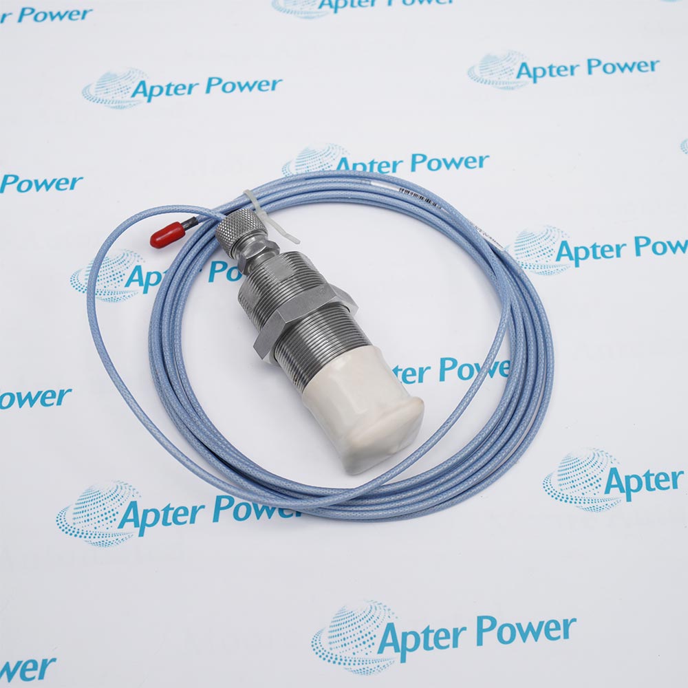
Product image is representative; revision or series may vary. Contact us to request a specific version.

Product Describe:

Bently Nevada 990-05-70-03-05 is a two-wire vibration transmitter with a 0-5 mils peak-to-peak span and a 7.0 m 3300 NSv transducer system.
  • Manufacturer part number
    990-05-70-03-05
  • Shipping
    Swift global dispatch
  • Condition
    New, original product
  • Shipping size (est.)
    9.8cm x 7.3cm x 5.8cm
  • Country of Origin
    USA
Get a quick price for 990-05-70-03-05
E-mail *
Mobile *
Company
Content *
Quantity *
Upload (gif, jpg, jpeg, png, bmp, doc, docx, xls, xlsx, ppt, pdf, csv)
For more information on how your data is processed and stored by Apterpower please read our privacy policy

What happens after you enquire

  • 0

    Review your reference

    Send the complete Bently Nevada 990-05-70-03-05 reference, label photographs and required quantity. Include the 0-5 mils peak-to-peak scale and 7.0 m transducer chain.

  • 1

    Confirm the offer

    Review the offered revision, condition, included items and documents against the confirmed installation.

  • 2

    Arrange dispatch

    Confirm quantity, dispatch date, lead-time start and delivery details in the quotation.

  • Match the complete marking

    Include the complete Bently Nevada 990-05-70-03-05 marking and any hardware revision on the item. Include the 0-5 mils peak-to-peak scale and 7.0 m transducer chain.

  • Check the offered item before ordering

    Request available label and connector photos. Have your maintenance team compare the offered 990-05-70-03-05 with the installed equipment and applicable Bently Nevada documentation.

Technical specifications for 990-05-70-03-05

  • Manufacturer:
    Bently Nevada
  • Product Category:
    Machinery Monitoring Systems
  • Spare Part Number:
    990-05-70-03-05
  • Weight:
    0.5 kg
  • Tariff Code:
    8537101190
  • Measurement:
    Radial vibration
  • Full-scale span:
    0-5 mils peak-to-peak
  • Electrical system length:
    7.0 m
  • Signal output:
    4-20 mA; two-wire
  • Terminal supply:
    +12 to +35 VDC
  • Maximum loop resistance:
    1000 ohms at 35 VDC; includes cable
  • Frequency response:
    5 Hz-6000 Hz; +0/-3 dB
  • Current limit:
    23 mA typical
  • Mounting:
    DIN clips and screws
  • Transmitter temperature:
    -35 to +85 degrees C
  • Fault current:
    Below 3.6 mA

Information

Overview Downloads Applications / Compatibility Product Precautions
  • Bently Nevada 990-05-70-03-05 brings radial shaft motion into the machinery controller through a powered current loop, while retaining a separate diagnostic connection for the probe signal.
Measurement span: 0-5 mils peak-to-peak
Transducer system: 7.0 m, compatible 3300 NSv probe and cable
Mounting: DIN clips and screws
The selected configuration combines a 0-5 mils peak-to-peak measurement span, a 7.0 m transducer system and din clips and screws. The integrated proximity conditioner accepts one compatible 3300 NSv probe with its matched extension cable; the probe lead and extension together establish the calibrated length.

The two-wire loop supplies power and transmits peak-to-peak shaft vibration amplitude as 4-20 mA. The receiving control system supplies the alarm and protection logic. Non-interacting zero and span adjustments support loop calibration, while the TEST input accepts a AC signal generator for controlled output checks.

The separate PROX OUT/COM and coaxial connection provide the dynamic and gap signal for diagnosis. This output is non-isolated and must be used with the specified test arrangement. Not OK/Signal Defeat drives the loop below 3.6 mA on a faulty transducer connection; power-up and fault recovery require approximately 2-3 seconds.
Controller platform reference: 3300 NSv transmitter system. Retain the calibrated chain and receiver scale.
The original technical excerpt for Bently Nevada 990-05-70-03-05 covers transmitter operation, electrical limits and diagnostic connections. The separate installation guide covers measurement scaling, loop burden, cable matching and controlled loop tests.
Original manufacturer pages retain their technical context. Use the Apter Power guide with the applicable manufacturer instructions and approved installation design.
System and supply context: 990-05-70-03-05 connects a matched NSv probe and extension to a powered current-loop receiver. Probe, cable, test adapter and receiving control equipment are separate unless included in the quotation.

Application scope: Use the 0-5 mils peak-to-peak scale for shaft-vibration supervision of the assigned machine point. Protective alarm logic remains in the receiving system.
Prepare Bently Nevada 990-05-70-03-05 for its configured installation using these checks.
Retain the measurement scale

Keep 0-5 mils peak-to-peak and its units in the receiver configuration.

Match the calibrated chain

The probe and extension together must equal 7.0 m.

Check loop burden

Provide the required terminal voltage after wiring and receiver losses.

Keep test grounding controlled

The diagnostic connection is non-isolated.

Recognize Not OK

Distinguish below-3.6 mA fault and startup states from valid measurements.

Restore protection deliberately

Remove test inputs and verify stable measurement before clearing the approved bypass.

Alternative Names

990 05 70 03 05 Bently Nevada 990-05-70-03-05

Technical notes

Calibration interaction: Recheck both zero and full scale after service, even though the adjustments are non-interacting. Verify the receiving controller scale independently.

Diagnostic loading: The buffered signal is calibrated for a high-impedance diagnostic instrument. Check test-lead length and instrument loading before interpreting a reduced signal.


FAQ View All FAQ

  • How should the two mounting provisions of 990-05-70-03-05 be used?
    The 03 selection supplies DIN clips and screws. Choose the installed mounting arrangement without changing the 7 m calibration or obstructing the field connections.
  • Can a velocity transmitter replace 990-05-70-03-05 without changing the receiver scale?
    No. This product represents peak-to-peak shaft displacement over 0-5 mils. Velocity units and signal conditioning describe a different measurement.
  • What happens if the zero adjustment of 990-05-70-03-05 is changed during calibration?
    Zero and span are non-interacting external adjustments. Verify both endpoints and the receiver scaling after making the controlled adjustment.
  • How is an AC generator connected to test 990-05-70-03-05?
    Use the dedicated TEST input under the transmitter procedure. This checks the loop output without treating the generator as a substitute for the installed probe chain.
  • Why must diagnostic loading be considered at the PROX OUT terminal of 990-05-70-03-05?
    PROX OUT has 10 kilohms output impedance and is calibrated for a 10 megohm load. Instrument loading can change the observed signal.
  • How long may the BNC diagnostic lead on 990-05-70-03-05 be?
    The specified maximum cable distance for the Proximitor output BNC connection is 3 m. This limit is separate from the 7 m calibrated probe system length.
  • What measurement bandwidth applies to 990-05-70-03-05?
    The frequency response is 5 Hz to 6000 Hz, +0/-3 dB. The receiving loop reports the conditioned peak-to-peak amplitude, not a sampled waveform.
  • Does the approval selection of 990-05-70-03-05 remove hazardous-area installation restrictions?
    No. The final 05 is the multiple-approvals selection. Apply only the classifications and wiring conditions actually marked on the supplied transmitter.
SPEAK TO OUR TEAM
Let’s find the right solution for you.
Send us the part number, quantity and delivery destination. Our team will help confirm availability and lead time.
  • Whatsapp: +86 18030235313

    Send us a message.
  • sales13@apterpower.com

    Complete our online form.
  • +86 18030235313

    Speak to our team in your native language.