-
Match the complete marking
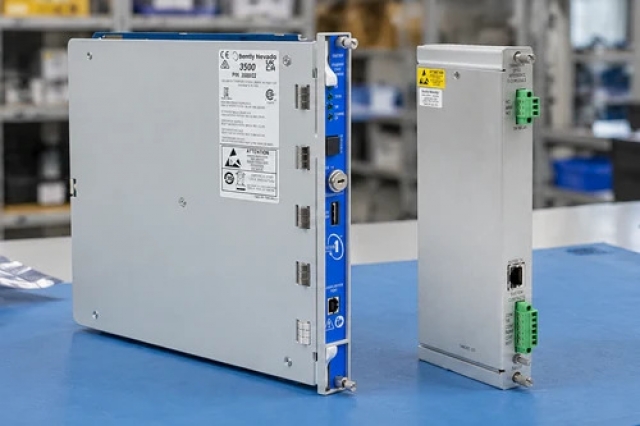
Compare the full Bently Nevada 330707-00-20-10-02-00 marking, hardware execution and mating interfaces with the installed position before approving a replacement.
-
Check the offered item before ordering
Request clear photographs of the offered 330707-00-20-10-02-00 marking and connections. Ask the maintenance team to compare them with the applicable Bently Nevada instructions and the installed circuit or system design.
Technical specifications for 330707-00-20-10-02-00
-
Manufacturer:Bently Nevada
-
Product Category:Machinery Monitoring Systems
-
Spare Part Number:330707-00-20-10-02-00
-
Weight:0.12 kg
-
Tariff Code:8537101190
-
Probe tip:11 mm
-
Mounting thread:5/8-18 UNF
-
Unthreaded length:0.0 in
-
Case length:2.0 in
-
Integral lead:1.0 m
-
Connector:Miniature coaxial ClickLoc, standard cable
-
Matched-system scale factor:3.94 V/mm (100 mV/mil)
-
Measurement principle:Non-contact eddy current
Information
- Its unarmored standard lead connects into the corresponding extension and Proximitor system; the probe itself is not a conditioned voltage-output instrument.
Mechanical interface: imperial threaded mounting with an unarmored lead
System integration: matched XL 11 mm components and monitor scaling
Upgrading a 7200-series 11 mm or 14 mm installation to XL 11 mm requires replacing the complete transducer component set and reviewing monitor configuration. A single new probe cannot establish that conversion. The retained system and its configured scale must match before protection service resumes.
Integrate with the appropriate target geometry and monitoring configuration for the longer-range system. Evaluate target material and geometry with the complete compatible transducer chain. Confirm target geometry, gap and monitor input configuration for the phase-reference application. A valid static displacement reading does not alone establish clean pulse detection.
330707-00-20-10-02-00 Original Technical Excerpt
Original Bently Nevada technical pages applicable to 330707-00-20-10-02-00 and its stated system context. PDF · 6 pages.330707-00-20-10-02-00 Installation & Verification Guide
Apter Power service guide covering identify the xl 11 mm chain; inspect the imperial mounting; support the unarmored lead and controlled acceptance. PDF · 5 pages.
Application scope: Applications must satisfy the module or transducer boundary and the actual controller, receiver or target conditions.
Axial position measurement
Use the matched XL 11 mm system where the application requires its displacement-measurement characteristics.Ramp differential expansion
Integrate with the appropriate target geometry and monitoring configuration for the longer-range system.Reciprocating rod position
Evaluate target material and geometry with the complete compatible transducer chain.Phase-reference sensing
Use an appropriate target and receiver configuration for repeatable event detection.
Record probe, extension and conditioner references with the monitor scale. Confirm the installation is not an unreviewed mixture with 7200-series components.
Check the 5/8-18 UNF interface and target alignment. Confirm surrounding metal and available adjustment do not compromise the intended sensing field.
Route the standard cable without abrasion or tensile load at the probe. Inspect ClickLoc contacts and restore the selected connection protection.

Use the appropriate target material and calibrated displacement reference. Compare conditioner output direction and proportional response over the intended operating interval.
Restore gap and channel settings, then perform the required position, vibration or phase-reference test. Retain the complete component identities and final response.
Keep the affected process in its approved maintenance state until field indications and the intended control or monitoring response have both been checked.
Alternative Names
Technical notes
Configuration scope: System ratings apply to the complete matched chain; mechanical and cable selections apply to 330707-00-20-10-02-00.
Engineering acceptance: The intended unarmored eddy-current proximity probe function must be accepted with its actual mating interfaces and configured system. Route the standard cable without abrasion or tensile load at the probe. Inspect ClickLoc contacts and restore the selected connection protection.

FAQ View All FAQ
-
Can 330707-00-20-10-02-00 be installed alone to convert a 7200-series measurement to XL 11 mm?No. The conversion requires the corresponding XL 11 mm probe, extension and conditioner, plus the applicable monitoring-system configuration changes.
-
Why should 330707-00-20-10-02-00 target material be checked before adjusting the gap?Eddy-current calibration depends on target properties. A different material can change the response even when the mechanical clearance appears correct.
-
Does fitting the 330707-00-20-10-02-00 thread prove compatibility with an existing conditioner?No. Mechanical fit and transducer electrical compatibility are separate. Match the XL 11 mm component family and total electrical length.
-
How can nearby metal affect a measurement made with 330707-00-20-10-02-00?Metal within the sensing field can alter the response independently of the intended target. Review mounting clearances and target geometry before interpreting the signal.
-
Why must 330707-00-20-10-02-00 be tested across a gap range rather than at one position?A single point can hide a scale or linearity mismatch. A controlled gap sweep checks the direction and proportionality of the complete transducer output.
-
What should be checked before using 330707-00-20-10-02-00 for a phase-reference target?Confirm target geometry, gap and monitor input configuration for the phase-reference application. A valid static displacement reading does not alone establish clean pulse detection.
-
How should 330707-00-20-10-02-00 unarmored lead be protected at the machine exit?Provide suitable routing and support against abrasion and pull loads. Standard cable construction does not provide the mechanical protection of an armored execution.
-
Why does changing the extension length behind 330707-00-20-10-02-00 require a system check?The probe lead and extension together form the conditioner’s electrical-length requirement. A changed cable length can alter calibration even if the connector type is unchanged.
Supporting new and legacy automation
-
Please try to be as accurate as possible with your search.
-
We can quote you on 1000s of specialist parts, even if they are not listed on our website.
-
We can't find any results for “”.
Related cases and sourcing guidance
View all case studiesYou May Also Like
Product Browsing History
-
Whatsapp: +86 18030235313
Send us a message. -
sales13@apterpower.com
Complete our online form. -
+86 18030235313
Speak to our team in your native language.