-
Match the complete marking
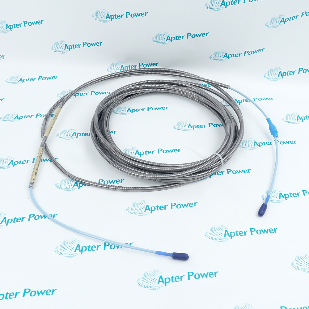
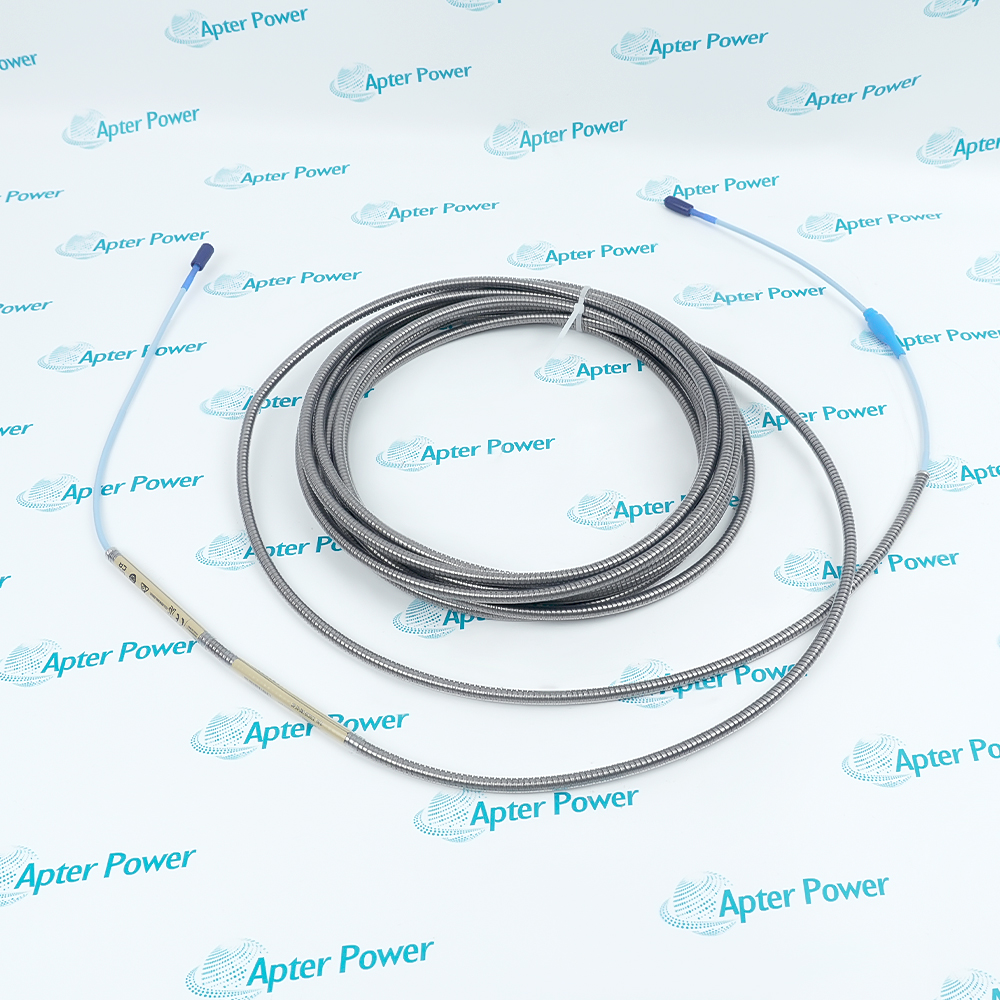
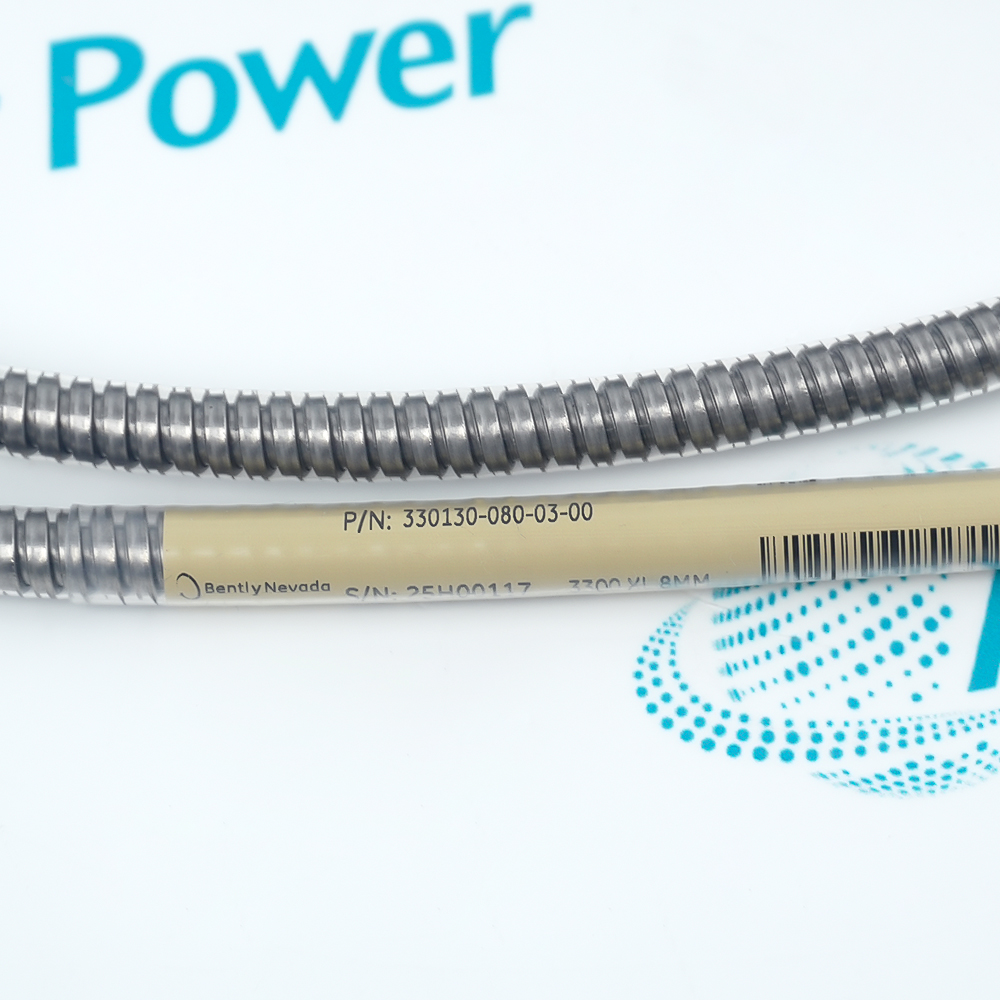
Compare the full Bently Nevada 330130-080-03-00 marking, hardware execution and mating interfaces with the installed position before approving a replacement.
-
Check the offered item before ordering
Request clear photographs of the offered 330130-080-03-00 marking and connections. Ask the maintenance team to compare them with the applicable Bently Nevada instructions and the installed circuit or system design.
Technical specifications for 330130-080-03-00
-
Manufacturer:Bently Nevada
-
Product Category:Machinery Monitoring Systems
-
Spare Part Number:330130-080-03-00
-
Weight:0.84 kg
-
Tariff Code:8537101190
-
Electrical cable length:8.0 m
-
Cable execution:Armored with connector protector
-
System family:3300 XL 8 mm
-
Interface:Coaxial ClickLoc
-
Matched length example:1.0 m probe + 8.0 m extension = 9.0 m system
-
Standard cable temperature limit:177 °C maximum, subject to complete-system limits
Information
- Its connector protector covers the cable junction, while the armor provides a protected cable execution along the route between the measurement point and conditioner.
Calibration role: retained electrical path between probe and conditioner
System boundary: measurement performance belongs to the matched transducer chain
The cable does not independently establish measurement sensitivity or linear range. Those values belong to the complete matched probe, extension and conditioner under the specified target and calibration conditions. Mixed standard and extended-temperature components must be evaluated against the appropriate complete-system accuracy limits.
Use the armored execution where the approved installation calls for cable protection. The connector protector supports the environmental arrangement at the probe-to-extension connection. Check the installed electrical lengths, connector condition and matching probe/conditioner family before mechanically regapping the probe to conceal a configuration error.
330130-080-03-00 Original Technical Excerpt
Original Bently Nevada technical pages applicable to 330130-080-03-00 and its stated system context. PDF · 7 pages.330130-080-03-00 Installation & Verification Guide
Apter Power service guide covering inventory the complete chain; plan the armored route; inspect coaxial contacts and controlled acceptance. PDF · 5 pages.
Application scope: Applications must satisfy the module or transducer boundary and the actual controller, receiver or target conditions.
Remote conditioner placement
Provide cable reach within a correctly selected electrical-length chain.Mechanically protected routing
Use the armored execution where the approved installation calls for cable protection.Protected probe junctions
The connector protector supports the environmental arrangement at the probe-to-extension connection.Retained XL 8 mm measurement
Replace a cable within the same matched family while preserving the probe and conditioner length relationship.
Record the probe lead and conditioner system lengths. Confirm the retained extension completes the required electrical total before removing the existing cable.
Provide a supported route that avoids crushing and abrasion. Preserve access to the protected junction without imposing tensile load on the probe lead.
Check the mating ClickLoc contacts for contamination or damage. Assemble using the intended finger-tight locking action and restore connector protection.

With an approved stationary target arrangement, compare conditioner output with the expected gap response. Investigate a shifted value before moving the probe mechanically.
Use the applicable controlled channel test and confirm stable response through the final routed cable. Retain the exact probe, cable and conditioner identities in the maintenance record.
Keep the affected process in its approved maintenance state until field indications and the intended control or monitoring response have both been checked.
Alternative Names
Technical notes
Configuration scope: System ratings apply to the complete matched chain; mechanical and cable selections apply to 330130-080-03-00.
Engineering acceptance: The intended armored proximity extension cable function must be accepted with its actual mating interfaces and configured system. Check the mating ClickLoc contacts for contamination or damage. Assemble using the intended finger-tight locking action and restore connector protection.

FAQ View All FAQ
-
Why does shortening 330130-080-03-00 change more than its routing length?The extension is part of the calibrated electrical path. Cutting or splicing changes that path and invalidates the intended component combination.
-
Can 330130-080-03-00 be selected solely because it reaches the conditioner?No. Probe lead length plus extension length must equal the conditioner’s specified system length. Check electrical length before assessing physical routing.
-
What does the connector protector on 330130-080-03-00 add beyond armor?It protects the junction environment. Armor and connector protection address different parts of the installation; an armored route does not make an exposed connection environmentally protected.
-
How should 330130-080-03-00 be assessed in a mixed standard and extended-temperature chain?Use the appropriate limits for the complete mixed system. An extended-temperature probe does not raise the standard cable’s temperature rating or preserve every standard-system accuracy figure.
-
Why should the ClickLoc connection of 330130-080-03-00 not be tightened with an arbitrary tool torque?The connector is designed to engage with finger-tight ClickLoc locking. Excessive tool force can damage the interface rather than improve its electrical connection.
-
What should be investigated if changing 330130-080-03-00 shifts the gap voltage?Check the installed electrical lengths, connector condition and matching probe/conditioner family before mechanically regapping the probe to conceal a configuration error.
-
Can 330130-080-03-00 provide shaft displacement directly to a PLC analog input?No. It carries the probe signal within the proximity-transducer chain. The matched conditioner provides the usable measurement output.
-
Why should cable-junction movement be tested when accepting 330130-080-03-00?Intermittent connector contact can mimic changing vibration or gap. Confirm stable output while inspecting the supported junction under a safe maintenance condition.
Supporting new and legacy automation
-
Please try to be as accurate as possible with your search.
-
We can quote you on 1000s of specialist parts, even if they are not listed on our website.
-
We can't find any results for “”.
Related cases and sourcing guidance
View all case studiesYou May Also Like
Product Browsing History
-
Whatsapp: +86 18030235313
Send us a message. -
sales13@apterpower.com
Complete our online form. -
+86 18030235313
Speak to our team in your native language.