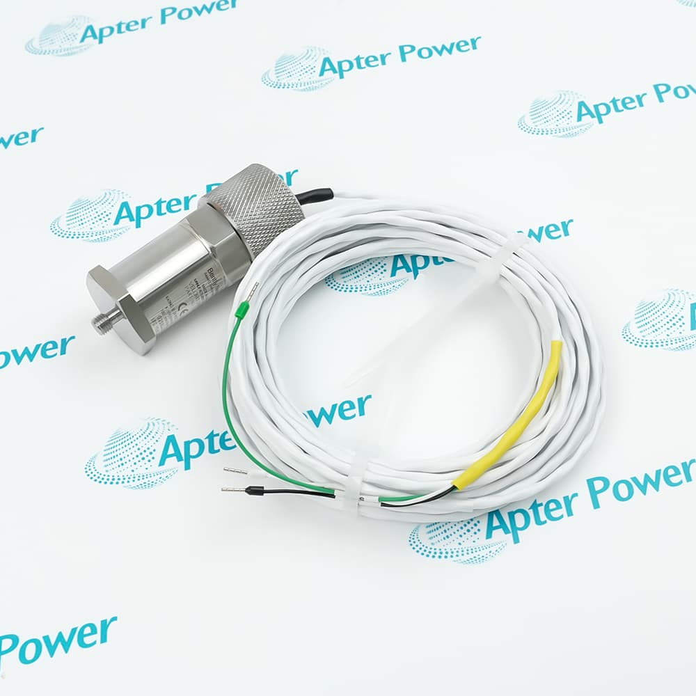
-
Match the complete marking
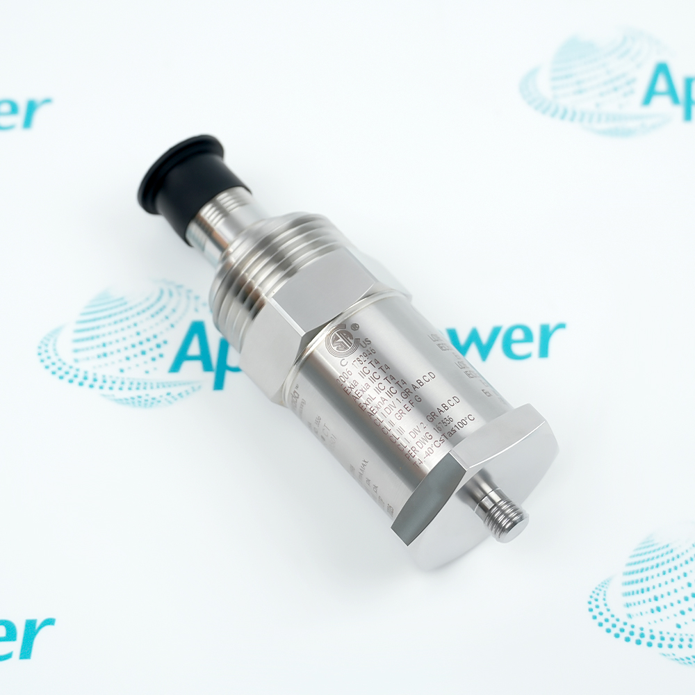
Include the full 190501-02-99-00 reference, mounting thread, receiving monitor and operating-speed range.
-
Check the offered item before ordering
Request label, sensor-base and connector photographs. Have your maintenance team compare the offered 190501-02-99-00 with the installed assembly and applicable Velomitor CT instructions.
Technical specifications for 190501-02-99-00
-
Manufacturer:Bently Nevada
-
Product Category:Machinery Monitoring Systems
-
Spare Part Number:190501-02-99-00
-
Weight:0.3 kg
-
Tariff Code:8537101190
-
Measurement output:Vibration velocity
-
Nominal sensitivity:3.94 mV/(mm/s), equivalent to 100 mV/(in/s)
-
Sensitivity tolerance:±5% at specified reference conditions
-
Tight-band frequency response:3–900 Hz, ±1.0 dB
-
Wide-band frequency response:1.5 Hz–1 kHz, ±3.0 dB
-
Peak velocity range:63.5 mm/s; frequency-dependent operating curves apply
-
Amplitude linearity:±2% through 63.5 mm/s peak
-
Typical thermal sensitivity change:−8% to +5% over operating range
-
Transverse response:Less than 5% of axial sensitivity
-
Mounted resonance:9 kHz minimum, stud mounted; quick disconnect excluded
-
Output bias:10.1 ±1.0 V DC, Pin A relative to Pin B
-
Typical dynamic output impedance:Less than 400 Ω
-
Broadband noise floor:0.229 mm/s peak over 1.5 Hz–1 kHz
-
Base-strain sensitivity:0.43 mm/s per microstrain
-
Electrical grounding:Internal electronics isolated from case
-
Operating temperature:−40 to +85 °C
-
Storage temperature:−40 to +100 °C
-
Shock limit:5000 g peak maximum
-
Humidity:100% condensing; not submerged
-
Case material:316L stainless steel
-
Mounting hardware:3/8–24 to 1/2–20 stud
-
Connection execution:included 32-foot cable
-
Mounting torque:4.5 ±0.6 N·m
-
Mounting orientation:Any orientation; sensing direction retained
-
Maximum stated cable example:305 m of cable 02173006 under stated conditions
-
Conditional cable recommendation:219 m at 4 in/s, 1 kHz and 200 pF/m
Information
- Bently Nevada 190501-02-99-00 extends velocity monitoring to slow-running fan structures where the measurement path must carry rotor motion to an accessible casing surface. The complete channel must retain that low-frequency response, not just the transducer’s nominal sensitivity.
Structural transmission: A representative casing or bearing-housing location must transmit the vibration relevant to protection.
Directional signal interpretation: Mounting direction and connector polarity define the sign used for phase comparison.
The narrow and wide frequency-response bands have different amplitude tolerances. Fan rotation, motor vibration and reducer components may occupy different parts of the response curve, so a single broadband number does not establish equal accuracy for all components. The receiving monitor’s filtering and amplitude convention must also be suitable for the speed and fault mechanism being evaluated.
The ordered 3/8–24 to 1/2–20 stud defines the connection between the sensor base and machine surface. The included 32-foot cable defines the supplied signal interface, while conduit adapters and protective housings remain separate accessories. Mounting stiffness, base strain, cable loading and environmental exposure affect the usable measurement; these conditions must be checked together before a channel is returned to protection.
190501-02-99-00 Official Velomitor CT Technical Excerpt
Original English velocity-response data, mounting and connection options, cable guidance and amplitude/frequency graphs. PDF · 10 pages.190501-02-99-00 Installation & Verification Guide
Apter Power field workbook covering structural transmission, mounting fit, cable/polarity checks, low-speed response and acceptance. PDF · 5 pages.
Application scope: These applications concern casing-transmitted vibration on slow fan systems and associated equipment. They do not establish shaft-relative displacement capability or universal detection of every rotor fault from every mounting location.
Cooling-tower fan assemblies
Evaluate low-speed casing vibration where the structural transmission path is adequate for the protection objective.Air-cooled heat-exchanger fans
Retain a suitably low-frequency monitoring path for slow fan rotation and associated harmonics.Fan motor and speed reducer
Assess components inside the usable velocity-response band without assuming the same tolerance at every frequency.Existing Velomitor CT channels
Restore the specified mounting and connection execution while preserving channel scaling, phase convention and filtering.
Check the vibration path from the component of concern to the proposed bearing-housing or casing location.
Match the ordered adapter and prepare a firm seating surface; resolve looseness or damaged threads before testing.
Check Pin A and Pin B throughout the signal path before comparing phase with a previous installation.
Evaluate capacitance, length, signal amplitude and frequency together; protect any necessary joints from moisture.
Test the complete channel at frequencies relevant to the fan speed rather than relying only on a mid-band calibration.
Account for high-frequency acceleration components, mounting strain and actual temperature before accepting a suspect signal.
Alternative Names
Technical notes
High-frequency overload: Vibration above 1 kHz exceeding 10 g peak can significantly reduce the available velocity range, even if the desired measurement component is at a lower frequency.
Cable statements: The 305 m specified-cable example and the 219 m recommendation at explicit amplitude, frequency and capacitance conditions are separate limits. Neither is a universal guarantee for every cable or waveform.
Mechanical strain: Base strain can create an apparent velocity contribution. Inspect seating, mounting stress and cable forces when the indication changes without a corresponding machine operating change.
Amplitude convention: Keep peak, RMS and peak-to-peak conventions consistent between the test reference and monitoring channel; nominal sensitivity alone does not define the displayed convention.

FAQ View All FAQ
-
Can the included cable of 190501-02-99-00 be treated as proof that every connected monitor will retain the low-frequency response?No. The monitor input and its filtering remain part of the measurement path. Check the configured low-frequency cutoff and compare the complete channel against an appropriate low-frequency reference before using the fan-speed component for protection.
-
Why can 190501-02-99-00 show a smaller fan-speed component at 90 rpm than expected from a 100 Hz calibration?90 rpm is 1.5 Hz, at the edge of the wider ±3 dB band rather than the tighter ±1 dB band. Include both sensor and monitor response in the comparison and test near the actual rotational frequency.
-
What should be checked if moving the cable of 190501-02-99-00 changes the indicated vibration?Inspect connector engagement, strain relief, shielding and mechanical force transmitted to the sensor base. Repeat the comparison with the cable secured; do not interpret a cable-dependent change as a rotor fault until the installation influence is resolved.
-
Can the output bias of 190501-02-99-00 be used as its required supply-voltage rating?No. Bias is the DC operating level of the signal interface, not a standalone power-input specification. Verify the compatible monitor or conditioning circuit and its approved wiring before connecting the sensor.
-
How should a low reading from 190501-02-99-00 be evaluated when another instrument reports high shaft vibration?The instruments may be measuring different quantities through different mechanical paths. Compare locations, directions, frequency bands and amplitude conventions; a weak casing transmission path can produce low casing velocity without proving low shaft motion.
-
What is the nominal electrical magnitude for a 10 mm/s test applied to 190501-02-99-00?It is 39.4 mV using nominal sensitivity. Keep the same peak or RMS convention at the reference and receiver, then assess deviations against the actual frequency, temperature and calibration conditions rather than a single ideal number.
-
Why can high-frequency vibration reduce the usable range of 190501-02-99-00 during a slow-fan test?Components above 1 kHz exceeding 10 g peak can reduce the available velocity range. Review out-of-band acceleration and clipping before assuming the low-frequency component alone determines the sensor loading.
-
Does the 32-foot cable supplied with 190501-02-99-00 remove the need to verify the delivered mounting assembly?No. The cable and mechanical options are independent. Compare the supplied 3/8–24 to 1/2–20 stud with the machine thread and sensor seating, then verify mounting torque and repeatable channel response after installation.
Supporting new and legacy automation
-
Please try to be as accurate as possible with your search.
-
We can quote you on 1000s of specialist parts, even if they are not listed on our website.
-
We can't find any results for “”.
Related cases and sourcing guidance
View all case studiesYou May Also Like
Product Browsing History
-
Whatsapp: +86 18030235313
Send us a message. -
sales13@apterpower.com
Complete our online form. -
+86 18030235313
Speak to our team in your native language.