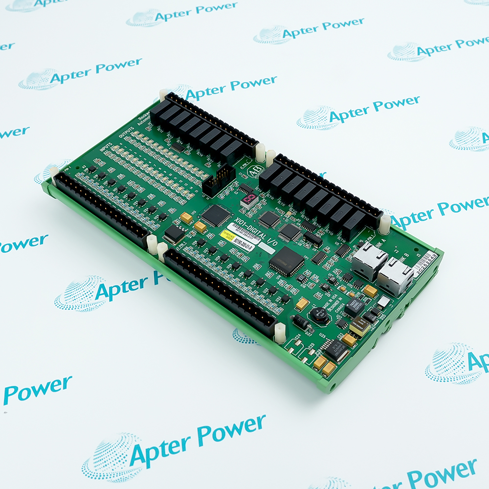
-
Match the complete marking
Include 80190-540-05-R and any revision or assembly number visible on the item. Keep the exact reference on your enquiry and quotation.
-
Check the offered item before ordering
Request available label and connector photos. Have your maintenance team compare the offered 80190-540-05-R with the installed equipment and applicable Allen-Bradley documentation.
Technical specifications for 80190-540-05-R
-
Manufacturer:Allen-Bradley
-
Product Category:General Automation
-
Spare Part Number:80190-540-05-R
-
Weight:0.04 kg
-
Tariff Code:8537101190
-
Board function:Temperature feedback (TFB)
-
Surface treatment:Conformal coating
-
System feedback transport:Fiber-optic path to the applicable FOI receiver
-
Inverter channel A reference:FOI-M-A, receiver RX7
-
Rectifier channel A reference:FOI-L-A, receiver RX7
-
Optional rectifier channel B:FOI-L-B, receiver RX7; configuration dependent
-
Inverter thermal warning setting:P316, applicable drive configuration
-
Inverter missing-feedback codes:Fault 180 when stopped; warning 220 while running
Information
- Allen-Bradley 80190-540-05-R supports maintenance of the thermal feedback chain. A credible temperature reading depends on the sensor, board power and optical return path, so signal loss must be separated from a real cooling problem.
Surface protection: Conformal coating
Diagnostic boundary: Sensor, board power and optical feedback path
In the applicable drive arrangement, inverter heatsink channel A returns to RX7 on FOI-M-A, while rectifier channel A returns to RX7 on FOI-L-A. The optional rectifier channel B uses RX7 on FOI-L-B and is not enabled on every drive. These are system connection references, not an assertion that this board is fitted in every channel.
Loss of the inverter optical temperature signal is identified as fault 180 while stopped and warning 220 while running. A high temperature is evaluated against the configured thermal thresholds, including inverter warning parameter P316. Check the sensor connection, board power and fiber integrity before treating a missing or implausible reading as actual overheating.
80190-540-05-R Original Technical Excerpt
Original PowerFlex 7000 thermal-diagnostic pages explain sensor, optical-feedback and cooling checks for the compatible system. PDF · 4 pages.80190-540-05-R Installation & Verification Guide
Apter Power preparation, connection assessment, diagnostic verification and handover guide. PDF · 5 pages.
Application scope: The channel references and alarm behavior below describe the drive system. They do not establish a universal board temperature range, sensor characteristic or TFB3 capability for every TFB.
Inverter thermal monitoring
Restore an approved inverter sensor-to-interface chain and confirm a plausible stopped-drive temperature.Rectifier cooling diagnosis
Separate excessive heatsink temperature from a loss of feedback before changing protection settings.Optical feedback restoration
Check receiver assignment, fiber seating and cable condition after maintenance in the power-converter cabinet.Sensor fault isolation
Compare the indicated temperature with the actual cooled condition and inspect sensor connection and resistance under the service procedure.
Retain the full -05-R reference, board revision and installed sensor arrangement.
Follow the medium-voltage drive isolation procedure before working around power-converter hardware.
Avoid bends, kinks, contamination and interchange of optical-channel connections.
A disconnected temperature sensor can appear as either a sensor fault or optical-feedback loss.
Do not raise alarm or trip thresholds to hide an unexplained temperature reading.
Inspect airflow and cooling condition when measured temperature is genuinely high.
Alternative Names
Technical notes
System-level data: FOI receiver names and diagnostic numbers refer to the applicable PowerFlex 7000 configuration.
Generation boundary: TFB3 adds gate-power-supply monitoring; that capability is not assumed solely from the TFB family name.
Thermal interpretation: A loss of temperature information and a measured overtemperature require different corrective actions.

FAQ View All FAQ
-
Does Allen-Bradley 80190-540-05-R have conformal coating?Yes. The -05-R service assembly is the conformal-coated TFB configuration.
-
What should be checked when the chain using Allen-Bradley 80190-540-05-R loses its optical signal?Check board and receiver power, fiber seating and cable condition, then the sensor connection. The failure can occur outside the feedback board.
-
Which inverter receiver is relevant when integrating Allen-Bradley 80190-540-05-R?For the applicable channel A arrangement, the receiver is RX7 on FOI-M-A. Confirm that this is the installed circuit before connecting the board.
-
Is optional rectifier channel B always available for Allen-Bradley 80190-540-05-R?No. That drive function is configuration dependent. Its system reference is RX7 on FOI-L-B and it is not normally used on every drive.
-
Why can a disconnected sensor near Allen-Bradley 80190-540-05-R produce an optical-loss fault?An absent sensor can produce an implausible temperature representation, so the drive may report sensor failure or missing optical feedback rather than a valid temperature.
-
How does the inverter missing-feedback response affect a system using Allen-Bradley 80190-540-05-R?The applicable drive diagnostics distinguish fault 180 while stopped from warning 220 during running. Diagnose the missing signal without assuming that the reading is an overtemperature.
-
Should P316 be increased after fitting Allen-Bradley 80190-540-05-R?Not as a remedy for an unexplained alarm. Compare actual temperature with the approved warning setting and inspect ventilation, sensor accuracy and the feedback chain.
-
Does the name TFB prove that Allen-Bradley 80190-540-05-R monitors SGCT gate supply?No. Gate-power monitoring is a generation-dependent TFB3 function and must be confirmed for the installed hardware and drive firmware.
Supporting new and legacy automation
-
Please try to be as accurate as possible with your search.
-
We can quote you on 1000s of specialist parts, even if they are not listed on our website.
-
We can't find any results for “”.
You May Also Like
Product Browsing History
-
Whatsapp: +86 18030235313
Send us a message. -
sales13@apterpower.com
Complete our online form. -
+86 18030235313
Speak to our team in your native language.