Speak to a sourcing specialist
sales13@apterpower.com

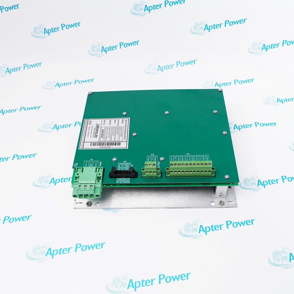
80190-560-02-R

Analog Control Board
Ships by Saturday, November 7
Product image is representative; revision or series may vary. Contact us to request a specific version.

Product Describe:

Allen-Bradley 80190-560-02-R is the conformal-coated analog control board for non-18-pulse PowerFlex 7000 drives. It connects analog feedback and the drive processing system within the matching converter configuration.
  • Manufacturer part number
    80190-560-02-R
  • Shipping
    Swift global dispatch
  • Condition
    New, original product
  • Shipping size (est.)
    38.6cm x 28.3cm x 5cm
  • Country of Origin
    USA
Get a quick price for 80190-560-02-R
E-mail *
Mobile *
Company
Content *
Quantity *
Upload (gif, jpg, jpeg, png, bmp, doc, docx, xls, xlsx, ppt, pdf, csv)
For more information on how your data is processed and stored by Apterpower please read our privacy policy

What happens after you enquire

  • 0

    Review your reference

    Send the complete 80190-560-02-R reference, revision, label and connector photographs, and required quantity.

  • 1

    Confirm the offer

    Compare the offered 80190-560-02-R configuration, condition, included parts and technical documents with your installation.

  • 2

    Arrange dispatch

    Confirm quantity, dispatch date, lead-time start and delivery details in the quotation.

  • Match the complete marking

    Include 80190-560-02-R and any revision or assembly number visible on the item. Keep the exact reference on your enquiry and quotation.

  • Check the offered item before ordering

    Request available label and connector photos. Have your maintenance team compare the offered 80190-560-02-R with the installed equipment and applicable Allen-Bradley documentation.

Technical specifications for 80190-560-02-R

  • Manufacturer:
    Allen-Bradley
  • Product Category:
    General Automation
  • Spare Part Number:
    80190-560-02-R
  • Weight:
    0.82 kg
  • Tariff Code:
    8537101190
  • Drive converter configuration:
    Non-18-pulse
  • Board coating:
    Conformal coating
  • Inverter analog self-test fault:
    186; diagnostic parameters P96 and P251
  • Rectifier analog self-test fault:
    128; diagnostic parameters P473, P474 and P494
  • Inverter conversion fault:
    189; ACB-to-slave-processor data transfer
  • Rectifier conversion fault:
    131; ACB-to-master-processor data transfer
  • Rectifier conversion sequence fault:
    133
  • Supported process-feedback path:
    4-20 mA or 0-10 V through the configured IFM

Information

Overview Downloads Applications / Compatibility Product Precautions
  • Allen-Bradley 80190-560-02-R supports the analog feedback path of a non-18-pulse PowerFlex 7000 drive. Startup self-tests and conversion diagnostics help distinguish input offsets from data-transfer faults.
Converter selection: Non-18-pulse PowerFlex 7000
Analog path: Feedback conversion with processor data transfer
Startup checks: Inverter and rectifier analog self-tests
The non-18-pulse selection separates this ACB from the 80190-560-01-R board used for 18-pulse drives. A shared board-family name does not establish interchangeability. Analog input wiring, converter topology and control revision must correspond to the installed PowerFlex 7000 configuration.

At startup, inverter analog self-test fault 186 identifies excessive DC offset through diagnostic parameters P96 and P251. Rectifier analog self-test fault 128 uses P473, P474 and P494 to identify affected feedback channels. The diagnostic words localize the channel before the associated feedback circuit is examined.

The analog-to-digital converters transfer feedback data to the drive processors. Fault 189 concerns transfer to the slave processor and fault 131 concerns transfer to the master processor within the sampling period. Process-feedback loss can also originate at the 4-20 mA or 0-10 V sensor, IFM wiring or IFM-to-ACB connection, so the board is only one part of the signal path.
Controller platform reference: PowerFlex 7000 analog control. Use the applicable installation instructions and approved system drawings.
Original PowerFlex 7000 pages cover the non-18-pulse ACB identity and analog self-test and conversion diagnostics. The separate installation guide covers topology matching, feedback-channel records and startup fault evaluation.
Original manufacturer pages retain their technical context. Use the Apter Power guide with the applicable manufacturer instructions and approved installation design.
System and supply context: Use this board only in its matching non-18-pulse PowerFlex 7000 control arrangement. Sensors, IFM modules and the DPM remain separate elements of the feedback chain.

Application scope: Applications below concern drive feedback integration and diagnosis. Signal ranges refer to the configured system input path and do not redefine every ACB connector as a universal analog input.
Prepare Allen-Bradley 80190-560-02-R for its configured installation using these checks.
Match topology

Confirm a non-18-pulse drive and the approved ACB revision before replacement.

Isolate the cabinet

Use the drive isolation and discharge procedure; board access is for qualified service personnel.

Map all connections

Label each feedback, control and IFM connection before removal.

Retain diagnostics

Capture self-test words and the complete fault sequence before clearing alarms.

Protect analog circuits

Use ESD handling and inspect connector alignment without modifying calibration components.

Verify the chain

Check input plausibility, conversion diagnostics and required interlocks before releasing the drive.

Alternative Names

80190-560-02-R Allen-Bradley 80190-560-02-R 8019056002R

Technical notes

Topology boundary: The -02-R board is the non-18-pulse selection. The -01-R 18-pulse ACB must not be treated as equivalent.

Self-test interpretation: The inverter and rectifier self-test words identify excessive feedback offsets and guide channel-level diagnosis.

Process input: A process-variable fault can arise at the sensor or IFM connection before the signal reaches the ACB.


FAQ View All FAQ

  • Can Allen-Bradley 80190-560-02-R replace the 18-pulse ACB?
    No interchangeability should be assumed. This part is the non-18-pulse selection; the 18-pulse ACB has a different part reference.
  • Which feedback words help diagnose fault 186 with Allen-Bradley 80190-560-02-R?
    Use InvAnlg SelfTst1 P96 and InvAnlg SelfTst2 P251 to identify inverter feedback channels with excessive DC offset.
  • How is the rectifier self-test localized on Allen-Bradley 80190-560-02-R?
    For fault 128, inspect RecAnlg SelfTst1 P473, SelfTst2 P474 and SelfTst3 P494 before examining the corresponding feedback circuit.
  • What does fault 189 mean in the analog path using Allen-Bradley 80190-560-02-R?
    The analog-to-digital data was not completely transferred from the ACB to the slave processor by DMA within the sampling period.
  • How does fault 131 differ from fault 189 for Allen-Bradley 80190-560-02-R?
    Fault 131 concerns the rectifier conversion path to the master processor; fault 189 concerns the inverter path to the slave processor.
  • Should a process-variable loss immediately condemn Allen-Bradley 80190-560-02-R?
    No. Check the configured sensor signal, IFM wiring and IFM-to-ACB connection first. A fault upstream of the board can produce the same missing feedback.
  • What signal types can reach Allen-Bradley 80190-560-02-R through the configured process IFM?
    The drive process-feedback path can use 4-20 mA or 0-10 V. Use the installed IFM and wiring configuration to determine the correct input.
  • Why retain the fault sequence before servicing Allen-Bradley 80190-560-02-R?
    An offset self-test, conversion-sequence error and incomplete data transfer describe different failure mechanisms. Their order helps separate a sensor, ACB or processor-path issue.
Related reading

Related cases and sourcing guidance

View all case studies
Manufacturers

Product Browsing History

Revisit the products you recently viewed on Apter Power.
SPEAK TO OUR TEAM
Let’s find the right solution for you.
Send us the part number, quantity and delivery destination. Our team will help confirm availability and lead time.
  • Whatsapp: +86 18030235313

    Send us a message.
  • sales13@apterpower.com

    Complete our online form.
  • +86 18030235313

    Speak to our team in your native language.