-
Match the complete marking
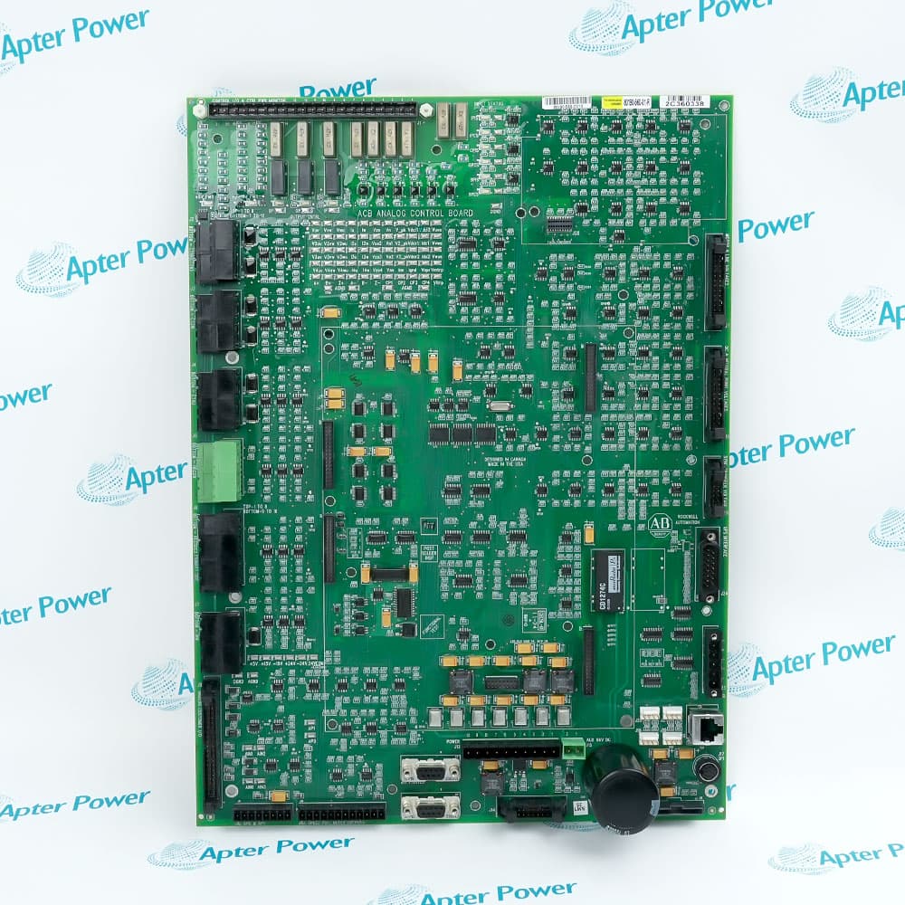
Match the full 80190-560-01-R reference with the installed 18-pulse PowerFlex 7000 ForGe ACB. Compare board revision, connector labels and frame-specific drawings before ordering.
-
Check the offered item before ordering
Request clear label and connector photographs. Have your maintenance team compare the offered 80190-560-01-R with the installed assembly and applicable Rockwell Automation PowerFlex 7000 instructions.
Technical specifications for 80190-560-01-R
-
Manufacturer:Allen-Bradley
-
Product Category:PLC Systems
-
Spare Part Number:80190-560-01-R
-
Weight:0.86 kg
-
Tariff Code:8537101190
-
Rectifier configuration:18-pulse
-
Isolated process inputs:3
-
Process input selections:−10/0/+10 V or 4–20 mA, individually configurable
-
Voltage-input impedance:75 kΩ
-
Current-input impedance:100 Ω
-
Required receiver compliance:At least 2 V at 20 mA, excluding external circuit drop
-
Individual input isolation:±100 V DC or 70 V RMS AC
-
Isolated process output:1 × 4–20 mA
-
Output loop compliance:12.5 V
-
Maximum receiver resistance:625 Ω at 20 mA; include external loop resistance
-
Non-isolated process outputs:4 × −10/0/+10 V
-
Minimum voltage-output load:600 Ω
-
Voltage-output reference:Drive AGND
-
Analog IFM connection:ACB J8
-
Line-current connector groups:J2: CT2U/CT2W; J3: CT3U/CT3W; J4: CT4U/CT4W
-
Motor-current connector:J5: HECSU/HECSW
-
DC-link current connector:J6: HECSDC1/HECSDC2
-
Air-pressure connector:J9: AP0/AP1
-
DPI interface connector:J16
-
XIO link connector:J22, CAN interface
-
Power LED D7:+5 V present
-
Power LED D9:±15 V OK
Information
- Allen-Bradley 80190-560-01-R occupies the signal-interface layer beneath the drive processor. Its replacement must preserve the association between the rectifier arrangement, feedback channels and external control circuits.
External interface: The IFM brings customer analog connections to the ACB while other connectors serve communication and control functions.
Diagnostic access: Labeled test points allow signal and supply checks without treating all reference terminals as interchangeable.
Customer analog circuits reach the board through the Interface Module. The isolated receiver channels accept independently selected current or voltage inputs, whereas the non-isolated process outputs share drive analog ground. Input mode, loop burden and the receiving instrument reference therefore determine whether a correctly wired signal will also measure correctly.
The ACB also supports communication connections, power-supply monitoring and the mechanical stack carrying the drive processor and encoder interface. Its D7 and D9 indicators describe particular supply conditions, not complete channel or system health. Following replacement, restore connector identity and validate both low-voltage control functions and the authorized drive-level test sequence.
80190-560-01-R Official ACB Technical Excerpts
English Rockwell Automation spare-part identification, ACB connections, test points, analog circuits and replacement instructions. PDF · 10 pages.80190-560-01-R Installation & Verification Guide
Apter Power checks for the 18-pulse installation, signal reference, loop loading, connector restoration and controlled release. PDF · 5 pages.
Application scope: The analog values below concern the B Frame ForGe control interfaces. Confirm frame-specific implementation and electrical drawings before extending those functions to another drive arrangement.
18-pulse control servicing
Restore the correct rectifier-specific ACB in an existing ForGe drive while retaining the installed line-feedback assignments.Plant analog integration
Interface supported process transmitter and receiver circuits through the IFM with matching current or voltage settings and a checked loop budget.Drive feedback diagnosis
Trace line, motor, DC-link and ground-fault channels separately when comparing physical signals with control observations.Control-cabinet communications
Maintain the documented terminal, DPI and XIO connections as part of the complete drive assembly; the ACB is not a standalone network controller.
Isolate and lock out all medium-voltage and control supplies using the approved drive procedure before board removal.
Identify the DPM and encoder-interface attachments and use the specified removal sequence; do not pull the ACB beneath connected boards.
Record each connector and its matching CT, motor, DC-link or voltage-feedback circuit before disconnection.
Distinguish AGND, DGND and supply commons; use the test point specified for the measurement being performed.
Provide appropriate isolation for non-isolated process outputs that leave the frame enclosure.
Restore interlocks, diagnostic connections and process scaling, then perform the authorized low- and medium-voltage tests before release.
Alternative Names
Technical notes
Isolation boundary: Input-channel isolation does not make the non-isolated voltage outputs floating. External instrument grounding must follow the output circuit design.
Terminal numbering: Analog connection numbers in the IFM diagrams refer to IFM terminals. They are not ACB test-point numbers or connector pin labels.
Supply diagnosis: D7 checks +5 V presence and D9 checks the ±15 V OK condition. A lit pair cannot prove the remaining supply rails, feedback sensors or communication links.
Assembly scope: Drive parameters and processor firmware belong to the DPM. Replacing or disturbing that assembly requires its own backup and restoration procedure.

FAQ View All FAQ
-
Can a 500 Ω receiver and 150 Ω cable loop be driven at 20 mA by 80190-560-01-R?The combined 650 Ω would require 13 V at 20 mA, exceeding the 12.5 V compliance of the described ForGe output. Reduce loop resistance or use suitable conditioning, then verify the high-end value under the real connected load.
-
Why can a 4–20 mA source work on a calibrator but fail at the 80190-560-01-R input?The 100 Ω current input needs 2 V at 20 mA before cable and other series drops are included. Check transmitter compliance with the complete circuit connected, not only the unloaded source or a lower-burden calibrator.
-
What error can a 5 kΩ voltage-source resistance introduce at 80190-560-01-R?With the 75 kΩ voltage-input impedance, a simple source divider passes 75/(75+5), or 93.75%, of the source voltage. That is 6.25% attenuation under this stated example; compare unloaded and connected voltages or provide a suitable buffer.
-
Why should a remote recorder connected to 80190-560-01-R voltage outputs use isolation?Those process outputs reference drive AGND. The ForGe instructions require isolation when they drive outside the frame enclosure. Verify the recorder reference and cable route instead of assuming that isolation of the input channels also applies to these outputs.
-
Can 80190-560-01-R be accepted solely because both power LEDs are lit?No. The two LEDs cover +5 V presence and the ±15 V OK condition. Verify the assigned feedback channels, other required supplies, communication paths and interlocks using the drive test procedure.
-
How should two similar line-current harnesses be distinguished during 80190-560-01-R replacement?Compare the harness labels and drive drawing against J2 CT2U/CT2W, J3 CT3U/CT3W and J4 CT4U/CT4W. Confirm the restored phase and group association before energization; connector resemblance does not establish interchangeable feedback paths.
-
Are IFM terminal numbers interchangeable with test-point numbers on 80190-560-01-R?No. IFM terminals identify customer connection points, whereas TP labels identify diagnostic nodes and J labels identify board connectors. Use the correct diagram for the task and trace both ends before applying a test signal.
-
What must be protected when the DPM is lifted to access 80190-560-01-R?Retain the drive configuration and label the DPM connections before the prescribed removal sequence. Use static-control measures and handle the multiway connectors without bending pins. If the processor is also replaced, follow its separate firmware and parameter-restoration procedure.
Supporting new and legacy automation
-
Please try to be as accurate as possible with your search.
-
We can quote you on 1000s of specialist parts, even if they are not listed on our website.
-
We can't find any results for “”.
Related cases and sourcing guidance
View all case studiesYou May Also Like
Product Browsing History
-
Whatsapp: +86 18030235313
Send us a message. -
sales13@apterpower.com
Complete our online form. -
+86 18030235313
Speak to our team in your native language.