-
Match the complete marking
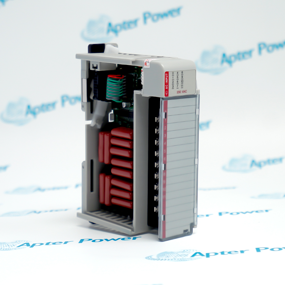
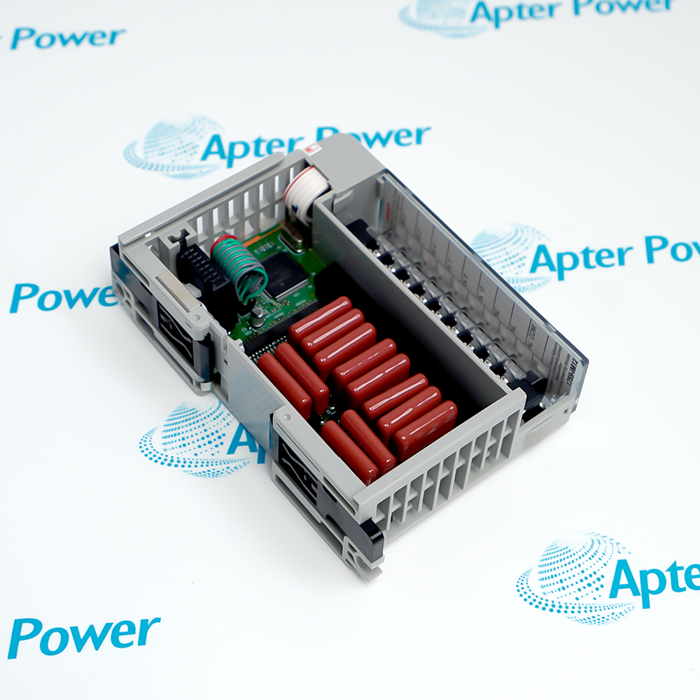
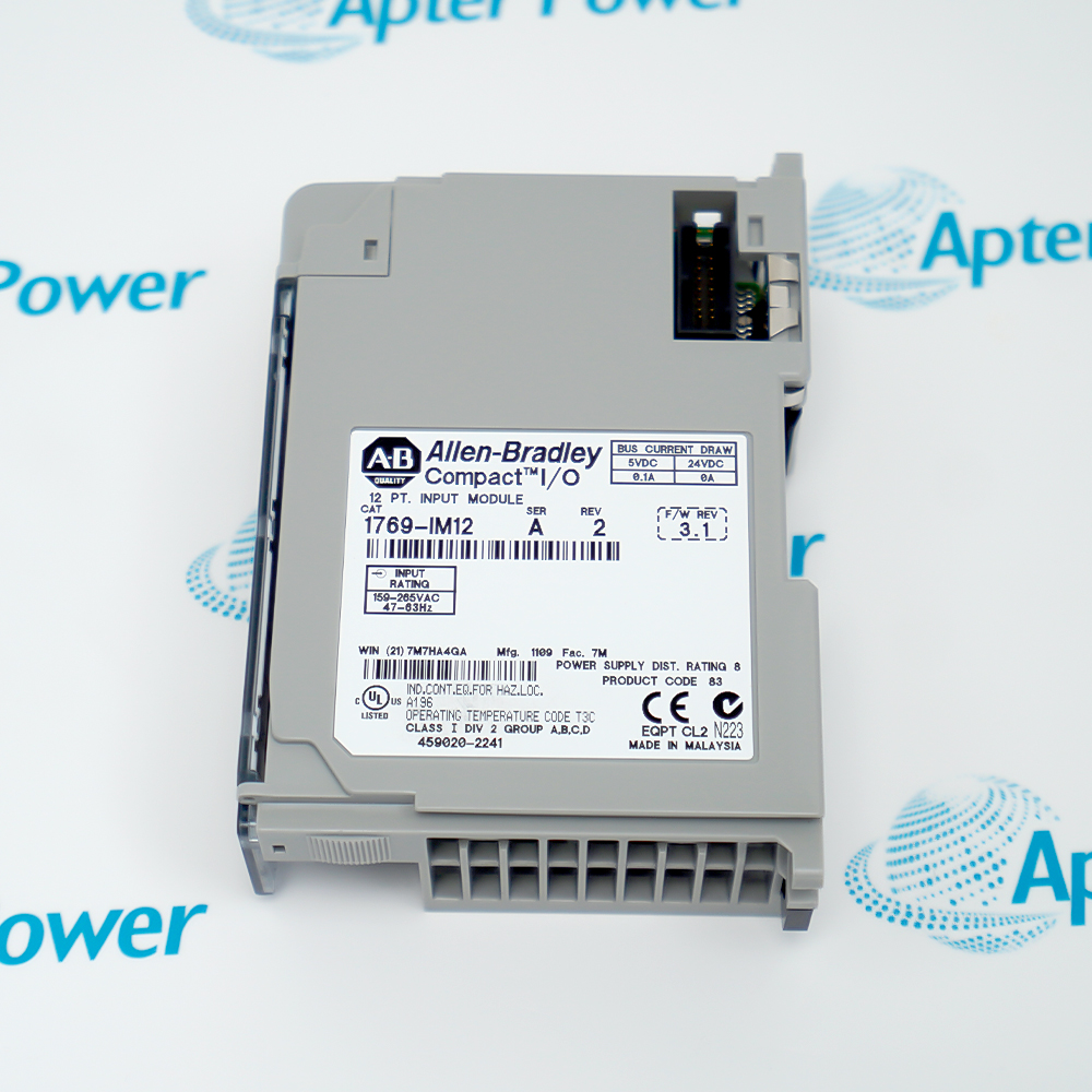
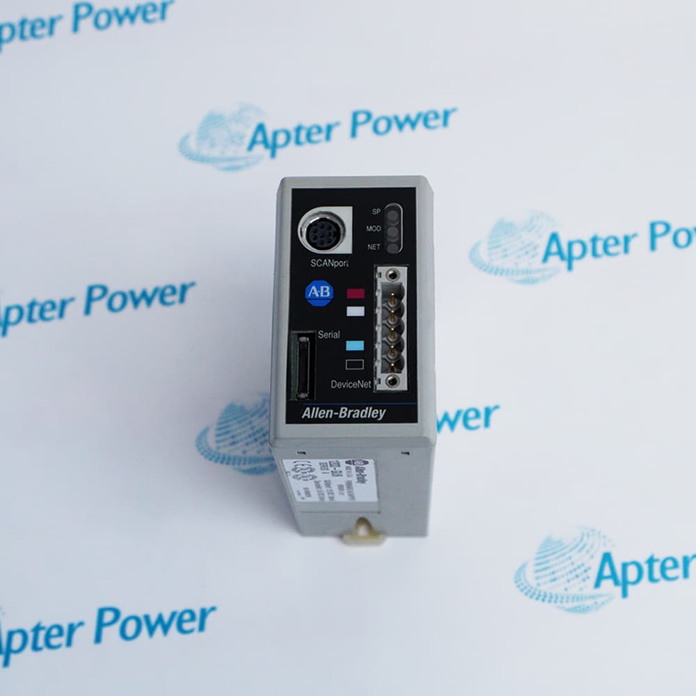
Compare the full Allen-Bradley 1769-IM12 marking, hardware execution and mating interfaces with the installed position before approving a replacement.
-
Check the offered item before ordering
Request clear photographs of the offered 1769-IM12 marking and connections. Ask the maintenance team to compare them with the applicable Allen-Bradley instructions and the installed circuit or system design.
Technical specifications for 1769-IM12
-
Manufacturer:Allen-Bradley
-
Product Category:PLC Systems
-
Spare Part Number:1769-IM12
-
Weight:0.2 kg
-
Tariff Code:8537101190
-
Inputs:12 in one common group
-
Voltage category:200/240 V AC
-
Operating input:159–265 V AC; 47–63 Hz
-
ON delay:20 ms
-
OFF delay:20 ms
-
Backplane current:100 mA at 5.1 V
-
OFF voltage:40 V AC maximum
-
OFF current:2.5 mA maximum
-
Power-supply distance:8 modules
-
Terminal screw torque:0.68 N·m
Information
- All twelve inputs share internally connected commons. It is therefore a grouped AC sensing interface, not twelve independent isolated circuits.
Timing behavior: account for both input transitions in the control sequence
Circuit review: distinguish AC common wiring from backplane power
Input ON and OFF delays suppress rapid transitions but also affect event capture. Leakage through switches or suppression components can keep an input above its intended OFF condition. Commissioning should verify the real disconnected and energized field states rather than relying only on a terminal continuity test.
Combine the field interface with the correct bus-power and assembly placement. Use input response together with controller timing when assessing the sequence. Check its supply-distance rating and the bank current budget, as well as mechanical bus engagement. A vacant mounting position alone does not establish compatibility.
1769-IM12 Original Technical Excerpt
Original Allen-Bradley technical pages applicable to 1769-IM12 and its stated system context. PDF · 4 pages.1769-IM12 Installation & Verification Guide
Apter Power service guide covering isolate the ac field circuits; inspect bank placement; verify voltage and frequency and controlled acceptance. PDF · 5 pages.
Application scope: Applications must satisfy the module or transducer boundary and the actual controller, receiver or target conditions.
Mains-level contact status
Acquire compatible AC circuit states through the shared-common input group.Compact I/O cabinet installations
Combine the field interface with the correct bus-power and assembly placement.Timed AC sequence feedback
Use input response together with controller timing when assessing the sequence.Existing grouped AC wiring
Retain the circuit common and protective arrangements rather than treating points as separately isolated inputs.
Identify the shared common and all energized sources. Establish the approved isolation state before loosening terminals or moving the module.
Check the power-supply distance and backplane-current allocation. Secure the bus connection and the mechanical mounting with power isolated.
Measure the intended AC source under controlled conditions. Confirm compatibility with the operating range before connecting field contacts.

Check each real field circuit for valid ON and OFF conditions, including leakage through connected suppression components. Leave all NC terminals unused.
Exercise both transitions through the controller program. Restore protections and retain the acceptance result for the complete AC sensing circuit.
Keep the affected process in its approved maintenance state until field indications and the intended control or monitoring response have both been checked.
Alternative Names
Technical notes
Configuration scope: Technical values apply to 1769-IM12 with the stated operating conditions. Check supplied revision and the configured installation.
Engineering acceptance: The intended ac digital input module function must be accepted with its actual mating interfaces and configured system. Measure the intended AC source under controlled conditions. Confirm compatibility with the operating range before connecting field contacts.

FAQ View All FAQ
-
Why must 1769-IM12 commons not be treated as independent isolated returns?They are connected internally for the twelve-point group. Review the connected AC circuits as a common-reference arrangement before combining field sources.
-
Can a short AC pulse be reliably captured by 1769-IM12 regardless of duration?No. The input response and controller scan impose timing constraints. Use a suitable event-input arrangement if the pulse is shorter than the accepted acquisition interval.
-
How can a suppression component keep 1769-IM12 indicating ON after a contact opens?Leakage through the field circuit can maintain voltage or current above the OFF-state limits. Test the actual open-contact condition with all connected components present.
-
Why should 1769-IM12 be checked against line frequency as well as voltage?The AC input has a defined operating-frequency range. A source within the voltage range but outside the frequency conditions is not automatically acceptable.
-
Can an unused 1769-IM12 NC terminal serve as a convenient wiring junction?No. Leave terminals marked NC unused. Use an appropriate external terminal point for unrelated connections.
-
What must be reviewed if 1769-IM12 is relocated within a Compact I/O bank?Check its supply-distance rating and the bank current budget, as well as mechanical bus engagement. A vacant mounting position alone does not establish compatibility.
-
How should 1769-IM12 input timing be included in a machine sequence test?Exercise both energization and de-energization with the real controller scan and logic. Verify that the combined delay still meets the sequence requirements.
-
Why is a DC test source inappropriate for accepting 1769-IM12 field operation?The module is an AC voltage input with specified frequency conditions. Use a controlled, suitable AC test arrangement that represents the intended circuit.
Supporting new and legacy automation
-
Please try to be as accurate as possible with your search.
-
We can quote you on 1000s of specialist parts, even if they are not listed on our website.
-
We can't find any results for “”.
Related cases and sourcing guidance
View all case studiesYou May Also Like
Product Browsing History
-
Whatsapp: +86 18030235313
Send us a message. -
sales13@apterpower.com
Complete our online form. -
+86 18030235313
Speak to our team in your native language.