-
Match the complete marking
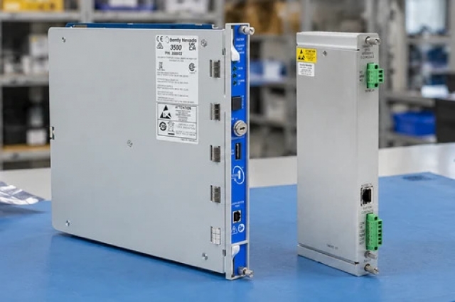
Provide the complete ABB PM864AK02 3BSE018164R1 marking. Match the complete kit number and identify both processor/baseplate assemblies.
-
Check the offered item before ordering
Request available label and connector photos. Have your maintenance team compare the offered PM864AK02 3BSE018164R1 with the installed equipment and applicable ABB instructions.
Technical specifications for PM864AK02 3BSE018164R1
-
Manufacturer:ABB
-
Product Category:PLC Systems
-
Spare Part Number:PM864AK02 3BSE018164R1
-
Weight:0.5 kg
-
Tariff Code:8537101190
-
Processor architecture:MPC862
-
CPU clock:96 MHz
-
SDRAM:32 MB per processor
-
Firmware flash:2 MB per processor
-
Control-network ports:2 × RJ45 Ethernet per TP830
-
Serial interfaces:COM3 RS-232C; isolated COM4 configuration port
-
COM3 data rate:Up to 19,200 baud
-
COM4 data rate:9,600 baud
-
Communication expansion:CEX-Bus
-
CPU arrangement:Redundant primary/backup pair
Information
- ABB PM864AK02 3BSE018164R1 maintains a paired controller arrangement in which the backup processor is coordinated with the primary through a dedicated redundancy connection.
Processing: MPC862 at 96 MHz
Expansion: Ethernet, serial and CEX-Bus interfaces
Each TP830 baseplate provides CN1 and CN2 Ethernet connections plus COM3 and COM4 serial ports. COM3 is RS-232C with modem-control signals; COM4 is an isolated service/configuration connection. CEX-Bus interfaces extend communication beyond the built-in ports.
The K02 arrangement is a redundant processor kit. Its CPU pairing, RCU link, power arrangement and communication topology must be engineered together. The direct electrical ModuleBus arrangement for a single CPU must not be assumed valid for a redundant CPU installation.
PM864AK02 3BSE018164R1 Official Technical Excerpt
ABB PM864AK02 3BSE018164R1: original manufacturer technical information covering the specified interfaces and operating limits. PDF · 10 pages.PM864AK02 3BSE018164R1 Installation & Verification Guide
Apter Power installation and verification guide covering identify the processor pair, trace the rcu connection, restore the control network, establish compatible controller states, check the i/o architecture. PDF · 5 pages.
Application scope: The applications below describe its technical role. Select associated hardware and configuration for the actual installation.
Redundant process control
Use paired processors where the control application requires an engineered backup CPU.Control-network integration
Connect the TP830 Ethernet ports to the designed AC 800M network arrangement.Communication expansion
Attach supported interfaces through the CEX-Bus and preserve its power and termination plan.Installed-system maintenance
Replace a processor within the existing redundancy architecture while retaining the application and firmware pairing.
Back up the controller application and retain firmware versions, network settings and redundancy state. Establish the permitted plant operating condition before changing either processor.
Record communication-interface order, termination and any BC810 interconnection arrangement. Check the intended topology before disturbing a controller or baseplate connection.
Use the appropriate COM4 configuration connection and its 9,600-baud setting. Keep COM3 process or modem communication separate from service activities.
Use the site's controlled redundancy test to assess transfer of the control task. Observe process continuity, communication quality and application alarms rather than relying only on a green indicator.
Save the tested CPU states, application backup, firmware identities, RCU/CEX layout and communication results. Release the system only when both normal operation and the intended backup behavior are established.
Verify that the installed I/O uses a supported redundant-controller arrangement. Do not add a single-CPU electrical ModuleBus cluster without confirming its applicability to the pair.
Alternative Names
Technical notes
Operating boundary: The processor clock and raw memory capacity do not specify a guaranteed control-task cycle time; that depends on the configured application and communication load.
Integration details: Retain CPU firmware, application compatibility, TP830 network identities, RCU connectivity and the engineered I/O topology as one replacement boundary.
Technical basis: ABB AC 800M 5.1 Controller Hardware Product Guide, 3BSE036352-510 A. PM864A controller architecture and the PM864AK02 redundant-kit identity apply. CPU memory and performance must be matched to the installed firmware and application configuration.

FAQ View All FAQ
-
Is the 32 MB memory of PM864AK02 3BSE018164R1 entirely available for application code?No. It is the SDRAM hardware capacity per processor. Firmware, runtime data and the configured application share the available memory resources.
-
What connects the paired processors in PM864AK02 3BSE018164R1?The redundant arrangement uses an RCU link between the processors in addition to the engineered CEX-Bus and control-network connections.
-
How do COM3 and COM4 differ on PM864AK02 3BSE018164R1?COM3 supports RS-232C communication with modem-control signals. COM4 is isolated and serves the configuration connection at 9,600 baud.
-
Can PM864AK02 3BSE018164R1 use the same direct electrical ModuleBus arrangement as a single CPU?Do not assume so. The direct electrical ModuleBus connection is specified for a single CPU arrangement; redundant CPU I/O topology needs its corresponding supported configuration.
-
What is the purpose of CN1 and CN2 on PM864AK02 3BSE018164R1?They provide the TP830 control-network Ethernet connections. Their use must follow the engineered network and redundancy arrangement.
-
Does fitting a second CPU alone complete the redundancy of PM864AK02 3BSE018164R1?No. Processor pairing, the RCU link, power, firmware and application configuration must all form a valid redundant system.
-
How are additional communication interfaces connected to PM864AK02 3BSE018164R1?Compatible communication interfaces are connected through the CEX-Bus, rather than by treating the serial or Ethernet connectors as interchangeable buses.
-
Why should the firmware of both CPUs in PM864AK02 3BSE018164R1 be checked together?The pair must operate with a compatible firmware and application arrangement. Hardware identity alone does not demonstrate that the backup can take over the configured control task.
Supporting new and legacy automation
-
Please try to be as accurate as possible with your search.
-
We can quote you on 1000s of specialist parts, even if they are not listed on our website.
-
We can't find any results for “”.
Related cases and sourcing guidance
View all case studiesYou May Also Like
Product Browsing History
-
Whatsapp: +86 18030235313
Send us a message. -
sales13@apterpower.com
Complete our online form. -
+86 18030235313
Speak to our team in your native language.