Speak to a sourcing specialist
sales13@apterpower.com

ADV551-P00 S2

Digital Output Module
Ships by Friday, November 6
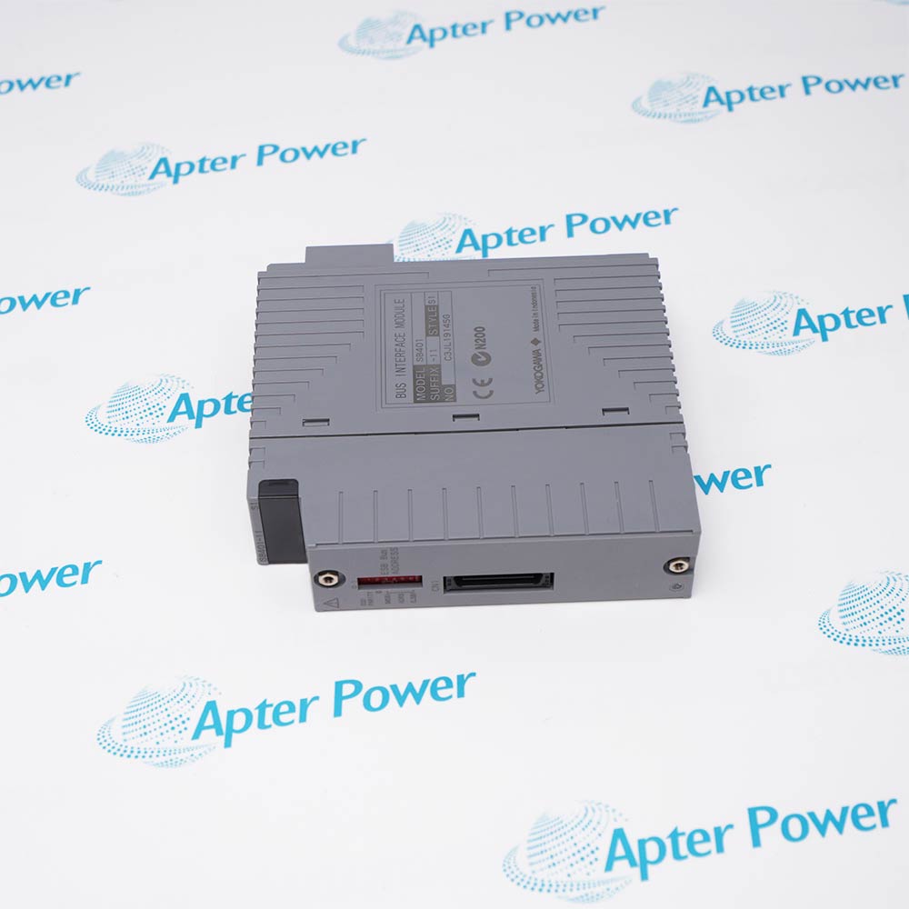
Product image is representative; revision or series may vary. Contact us to request a specific version.

Product Describe:

Yokogawa ADV551-P00 S2 is a CENTUM FIO digital output module. The ADV551-P design provides 32 current-sink outputs with status, pulse-width and time-proportioning functions.
  • Manufacturer part number
    ADV551-P00 S2
  • Shipping
    Swift global dispatch
  • Condition
    New, original product
  • Shipping size (est.)
    3.1cm × 10.6cm × 13cm
  • Country of Origin
    Japan
Get a quick price for ADV551-P00 S2
E-mail *
Mobile *
Company
Content *
Quantity *
Upload (gif, jpg, jpeg, png, bmp, doc, docx, xls, xlsx, ppt, pdf, csv)
For more information on how your data is processed and stored by Apterpower please read our privacy policy

What happens after you enquire

  • 0

    Review your reference

    Send the complete ADV551-P00 S2 reference, label photos and required quantity.
  • 1

    Confirm the offer

    Review the offered revision, condition, included items and documents.
  • 2

    Arrange dispatch

    Confirm quantity, dispatch date, lead-time start and delivery details in the quotation.
  • Match the complete marking

    Include ADV551-P00 S2 and any series, revision or assembly markings. Keep the complete reference on your enquiry and quotation.
  • Check the offered item before ordering

    Request available label, connector and mounting photos. Have your maintenance team compare the offered ADV551-P00 S2 with the installed equipment and applicable Yokogawa documentation.

Technical specifications for ADV551-P00 S2

  • Manufacturer:
    Yokogawa
  • Product Category:
    DCS Systems
  • Spare Part Number:
    ADV551-P00 S2
  • Weight:
    0.18 kg
  • Tariff Code:
    8537101190
  • Product series:
    CENTUM FIO
  • Reference design:
    ADV551-P
  • Base-design output channels:
    32
  • Output format:
    Current sink
  • Base applied voltage:
    24 V DC
  • Base external supply range:
    20.4 to 26.4 V DC
  • Base maximum channel load:
    100 mA/channel at 26.4 V
  • Maximum ON-state voltage:
    2 V DC (base design)
  • Maximum OFF-state leakage:
    0.1 mA (base design)
  • Output functions:
    Status / pulse width / time-proportioning
  • Base status response:
    3 ms maximum
  • Base pulse width:
    8 ms to 7200 s
  • Field connections:
    Pressure-clamp terminal / AKB331 / MIL cable

Information

Overview Downloads Applications / Compatibility Product Precautions
  • Yokogawa ADV551-P00 S2 transfers configured control commands from a FIO station to discrete field loads, with output behavior selected to suit the application.
Product type: Digital output module
Base-design channels: 32 current-sink outputs
Applied voltage: 24 V DC base rating
Functions: Status, pulse width and time-proportioning output
The ADV551 base design provides 32 transistor contact outputs in a current-sink arrangement. It uses an external 24 V DC supply, with a specified base-design supply range of 20.4 to 26.4 V DC. Field loads must be wired for the sink output convention and matched to the channel rating; the module is not a general-purpose relay-contact output board.

Status output, one-shot pulse-width output and time-proportioning ON/OFF output are available in the ADV551-P design. The reference gives a maximum 3 ms response for status output and 10 ms for mixed status/pulse operation. Pulse width spans 8 ms to 7200 s with 8 ms resolution, plus an ON/OFF delay of up to 1 ms. Function assignment and supported combinations depend on the node and configured pattern.

The reference output limit is 100 mA per channel at 26.4 V, with a maximum 2 V ON-state drop and 0.1 mA OFF-state leakage. A diode is required when driving a DC relay. Pressure-clamp terminals, an appropriate AKB331 dedicated cable or a MIL connector cable provide field connections. Dual-redundant use is supported for applicable configurations, but the mixed channel-by-channel pattern requires a direct-connected node and does not support dual redundancy.
Controller platform reference: Yokogawa CENTUM FIO. Match the installed module and system configuration.
Technical downloads for Yokogawa ADV551-P00 S2: a manufacturer technical excerpt and an Apter Power installation verification guide.
The technical reference preserves selected manufacturer pages. The installation guide is compiled by Apter Power for preparation and review; apply the original operating procedures and site controls during work.
Match ADV551-P00 S2 to the installed hardware and approved configuration before replacement or commissioning.
Check load polarity

Use wiring appropriate to current-sink outputs and verify field-supply polarity before energization.

Respect channel loading

The base-design limit is 100 mA per channel at 26.4 V. Include actual load demand and any inductive switching requirements.

Protect relay loads

Fit the required diode when driving a DC relay. Verify the field load and protection arrangement together.

Preserve output mode

Retain the approved channel pattern and timing. Do not assume every mixed pattern supports redundant operation.

Review terminal and cable ratings

Match pressure-clamp, AKB331 or MIL cable connections to the installed system. Cable ratings affect the complete connection specification.

Validate controlled outputs

Test outputs under a safe process condition and check pulse or time-proportioning behavior before final release.

Alternative Names

ADV551-P00 S2 ADV551-P00-S2 Yokogawa ADV551-P00 S2 Yokogawa ADV551-P00-S2

Technical notes

System relationship: Verify sink-output polarity, 24 V DC field supply and the current required by each load.

Configuration boundary: The technical data describes the ADV551 base design. Match the complete ADV551-P00 S2 marking, style and installed configuration; do not transfer later suffix approvals or ratings automatically.

Technical reference: Yokogawa Digital I/O Modules (for FIO), GS 33J60F70-01EN, 7th edition.

FAQ View All FAQ

  • What output arrangement does ADV551-P00 S2 use?
    The ADV551-P design has 32 current-sink transistor contact outputs. Field load polarity must match that arrangement.
  • What external supply range applies to the base design of ADV551-P00 S2?
    The ADV551 reference specifies 20.4 to 26.4 V DC, with a nominal applied voltage of 24 V DC.
  • What is the base-design channel load limit for ADV551-P00 S2?
    The maximum load current is 100 mA per channel at 26.4 V. Check the actual load and field connection arrangement.
  • Can ADV551-P00 S2 be used for pulse-width control?
    The ADV551-P design supports one-shot pulse-width and time-proportioning ON/OFF output as well as status output.
  • What pulse timing applies to the base design of ADV551-P00 S2?
    Pulse width is 8 ms to 7200 s at 8 ms resolution, with up to 1 ms additional ON/OFF delay in the reference design.
  • What protection is needed when ADV551-P00 S2 drives a DC relay?
    Connect the required diode for the DC relay load and verify the current rating and polarity before energization.
  • Can all output patterns on ADV551-P00 S2 be dual-redundant?
    No. The mixed channel-by-channel pattern is limited to direct-connected nodes and does not support dual redundancy. Use the approved pattern for the installed system.
  • Which field-connection methods are relevant to ADV551-P00 S2?
    The ADV551 base design supports pressure-clamp terminals, an appropriate AKB331 dedicated cable or a MIL connector cable. Cable ratings can limit the installation withstand specification.
Related reading

Related cases and sourcing guidance

View all case studies
Manufacturers

Product Browsing History

Revisit the products you recently viewed on Apter Power.
SPEAK TO OUR TEAM
Let’s find the right solution for you.
Send us the part number, quantity and delivery destination. Our team will help confirm availability and lead time.
  • Whatsapp: +86 18030235313

    Send us a message.
  • sales13@apterpower.com

    Complete our online form.
  • +86 18030235313

    Speak to our team in your native language.