Speak to a sourcing specialist
sales13@apterpower.com
Get a quick price for AAI141-S00
E-mail *
Mobile *
Company
Content *
Quantity *
Upload (gif, jpg, jpeg, png, bmp, doc, docx, xls, xlsx, ppt, pdf, csv)
For more information on how your data is processed and stored by Apterpower please read our privacy policy

What happens after you enquire

  • 1

    Requirement review

    We review the part number, quantity and delivery requirements and ask for any missing details.
  • 2

    Quotation and availability

    We confirm the proposed item, condition, availability, price and estimated lead time in the quotation.
  • 3

    Order confirmation and dispatch

    Once the quotation and purchasing details are agreed, your contact will coordinate the order and available dispatch information.

Technical specifications for AAI141-S00

  • Manufacturer:
    Yokogawa
  • Product Category:
    DCS Systems
  • Spare Part Number:
    AAI141-S00
  • Estimated shipping dimensions:
    3.3x10.7x13cm
  • Weight:
    0.28 kg
  • Tariff Code:
    8537101190
  • Counliy of origin:
    Japan
  • Input channels:
    16
  • Input signal:
    4 to 20 mA DC
  • Channel isolation:
    Non-isolated
  • Input update period:
    10 ms
  • Step response:
    100 ms
  • Allowable input:
    27 mA
  • Transmitter wiring:
    2-wire and 4-wire
  • External connection:
    Pressure clamp terminal, MIL cable or KS cable

Information

Overview Manuals Common Applications Product Precautions
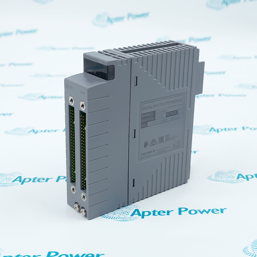
AAI141-S00 brings sixteen current loops into one FIO module position with a 10 ms update cycle and direct support for two-wire and four-wire transmitter circuits.
  • Acquires sixteen 4 to 20 mA process signals.
  • Updates the module data every 10 ms.
  • Accepts both two-wire and four-wire transmitter arrangements.
  • Uses a non-isolated channel architecture for the documented FIO application.

AAI141-S00 should be matched to the documented system position, companion hardware and retained project configuration before the channel or station is returned to control.

Important Notice: Preserve the complete AAI141-S00 identity and verify its documented electrical, network or signal response before release.

Yokogawa AAI141-S00 Manuals & Downloads
Yokogawa AAI141-S00 Official Technical Reference Excerpt (PDF)Yokogawa AAI141-S00 Installation & Commissioning Guide (PDF)

The first document covers the product function, system role and technical selection. The installation guide covers identification, connection checks, commissioning and the acceptance record.


Process transmitter inputs
Collects flow, pressure, level and temperature current signals.
FIO node modernization
Maintains a sixteen-loop analog input position in the documented node.
Two-wire loop integration
Connects powered transmitters through the approved terminal hardware.
Four-wire instrument inputs
Accepts independently powered 4 to 20 mA sources.
Before installing Yokogawa AAI141-S00, confirm the documented system, interfaces and controlled configuration.
1
Confirm the AAI141-S00 marking and assigned node slot.
2
Record all sixteen loop tags and terminal numbers.
3
Place affected process loops in the approved maintenance state.
4
Remove field power before changing pressure-clamp or cable connections.
5
Keep channel commons and shields in their documented positions.
6
Do not copy HART settings to this standard non-HART execution.
7
Inject controlled current points and compare every used channel.
8
Review open-loop diagnostics and controller quality before release.

Technical notes

Preserve the complete AAI141-S00 identity and verify its documented electrical, network or signal response before release.

FAQ View All FAQ

  • How many current loops does Yokogawa AAI141-S00 acquire?
    AAI141-S00 provides sixteen analog input channels.
  • Which field signal is assigned to Yokogawa AAI141-S00?
    The module accepts 4 to 20 mA DC current inputs.
  • Are the channels of Yokogawa AAI141-S00 individually isolated?
    No. The AAI141 channel architecture is non-isolated.
  • How quickly does Yokogawa AAI141-S00 refresh its input data?
    Its documented input update period is 10 ms.
  • What response time should be expected from Yokogawa AAI141-S00?
    The documented step response is 100 ms.
  • What maximum current may reach Yokogawa AAI141-S00 during checking?
    The allowable input is 27 mA; test equipment should remain within the documented limit.
  • Can Yokogawa AAI141-S00 accept both two-wire and four-wire transmitters?
    Yes. The documented wiring arrangements include two-wire and four-wire transmitters.
  • Which termination choices are documented for Yokogawa AAI141-S00?
    Pressure-clamp terminal blocks, MIL connector cabling and the dedicated KS cable arrangement are supported.
Related reading

Related cases and sourcing guidance

View all case studies
SPEAK TO OUR TEAM
Let’s find the right solution for you.
Send us the part number, quantity and delivery destination. Our team will help confirm availability and lead time.
  • Whatsapp: +86 18030235313

    Send us a message.
  • sales13@apterpower.com

    Complete our online form.
  • +86 18030235313

    Speak to our team in your native language.