Speak to a sourcing specialist
sales13@apterpower.com
Get a quick price for ADV151-P00 S2 ATD5A-00
E-mail *
Mobile *
Company
Content *
Quantity *
Upload (gif, jpg, jpeg, png, bmp, doc, docx, xls, xlsx, ppt, pdf, csv)
For more information on how your data is processed and stored by Apterpower please read our privacy policy

What happens after you enquire

  • 1

    Requirement review

    We review the part number, quantity and delivery requirements and ask for any missing details.
  • 2

    Quotation and availability

    We confirm the proposed item, condition, availability, price and estimated lead time in the quotation.
  • 3

    Order confirmation and dispatch

    Once the quotation and purchasing details are agreed, your contact will coordinate the order and available dispatch information.

Technical specifications for ADV151-P00 S2 ATD5A-00

  • Manufacturer:
    Yokogawa
  • Product Category:
    DCS Systems
  • Spare Part Number:
    ADV151-P00 S2 ATD5A-00
  • Estimated shipping dimensions:
    3.2×10.2×13cm
  • Weight:
    0.26 kg
  • Tariff Code:
    8537101190
  • Counliy of origin:
    Japan
  • Package function:
    Digital input with cable interface
  • Input channels:
    32
  • Rated input voltage:
    24 V DC sink/source
  • Input ON voltage:
    18 to 26.4 V DC
  • Input OFF voltage:
    5.0 V DC maximum
  • Maximum input voltage:
    30.0 V DC
  • Channel grouping:
    Two 16-channel common groups
  • Signal isolation:
    Input-to-system isolation
  • Module current:
    500 mA maximum at 5 V DC
  • Adapter function:
    External terminal-board interface
  • Redundancy:
    Dual-redundant module configuration

Information

Overview Manuals Common Applications Product Precautions
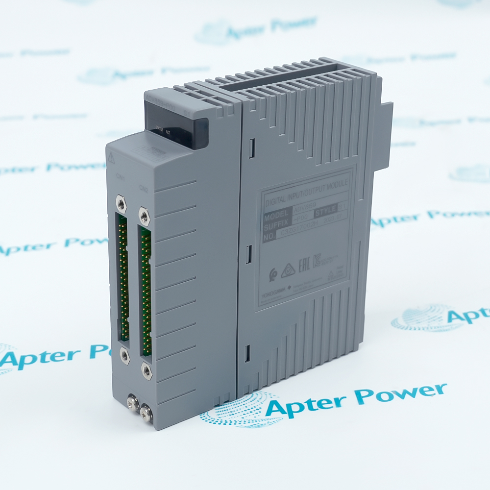
Yokogawa ADV151-P00 S2 ATD5A-00 is a coordinated field-connection package: the ADV151 module performs digital input acquisition while ATD5A-00 transfers the thirty-two channels into a dedicated cabled terminal-board path.
  • The module and adapter retain separate identities and service boundaries.
  • Thirty-two 24 V DC inputs travel through the documented AKB331 cable route.
  • Two sixteen-channel common groups preserve one shared polarity rule.
  • External termination can be maintained without treating the adapter as signal-processing hardware.

The ADV151 electrical limits govern field acquisition; ATD5A-00 governs how those signals enter the dedicated cable and external termination hardware. A valid replacement therefore matches both component tags, the cable, remote board, channel map and any redundant module arrangement.

Important Notice: Confirm ADV151-P00 S2 and ATD5A-00 separately. Do not describe ATD5A-00 as an internal feature of ADV151, and do not substitute another cable or terminal-board path without the approved engineering record.

Yokogawa ADV151-P00 S2 ATD5A-00 Manuals & Downloads
Yokogawa ADV151-P00 S2 ATD5A-00 Official Technical Reference Excerpt (PDF)Yokogawa ADV151-P00 S2 ATD5A-00 Installation & Commissioning Guide (PDF)

The official excerpt confirms the ADV151 input characteristics and the /D5A00 option for ATD5A-00. The installation guide treats the module, adapter, AKB331 cable and external termination as a controlled assembly.


Remote digital-input terminationBring 32 isolated 24 V DC inputs from an external terminal board to ADV151 through ATD5A-00 and AKB331.
Cabinet retrofit retentionRestore an existing cabled FIO input path while preserving adapter, cable, terminal-board and channel identities.
Relay-board interface workRetain the documented ATD5A and AKB331 connection where a compatible relay-board design is installed.
Redundant input architectureUse the package on each approved side while keeping modules, adapters, cables and common groups uniquely identified.
ADV151-P00 S2 and ATD5A-00 are separate components in one cabled input path. Preserve both tags, cable identity, termination and common polarity.
1
Record both ADV151-P00 S2 and ATD5A-00 component tags before disturbing the assembly.
2
Place every affected input in the approved maintenance state and isolate hazardous external 24 V DC sources.
3
Label the node, slot, ATD5A connector, AKB331 cable ends and external terminal-board position as one path.
4
Record inputs 1-32 and the two common groups; both externally supplied common groups must use the same polarity.
5
Do not exceed ADV151's documented 30.0 V DC maximum input or assign signal-processing specifications to ATD5A-00.
6
Inspect the adapter and cable connector for damage or contamination before reconnecting the external termination path.
7
For redundant service, keep every module, adapter and cable assigned to its recorded side and slot.
8
After restoration, verify permitted OFF/ON states, common polarity, cable continuity, node diagnostics and redundant behavior before release.

Technical notes

This listing represents an ADV151-P00 S2 module together with the ATD5A-00 adapter, not a single integrated device. ADV151 receives 32 isolated 24 V DC inputs in two same-polarity 16-channel common groups. ATD5A interfaces the module to an external terminal board through AKB331. Verify both component tags and the complete cable/terminal-board architecture.

FAQ View All FAQ

  • What components are included in Yokogawa ADV151-P00 S2 ATD5A-00?
    The listing combines one ADV151-P00 S2 32-channel digital input module with one ATD5A-00 KS cable interface adapter. They remain separate components in the installed architecture.
  • What field-signal role does Yokogawa ADV151-P00 S2 ATD5A-00 provide?
    The ADV151 module receives 32 isolated 24 V DC sink or source inputs; ATD5A-00 provides the cabled interface to the external terminal-board side.
  • Which cable is used with Yokogawa ADV151-P00 S2 ATD5A-00?
    The documented dedicated cable for the ADV151 and ATD5A external terminal-board path is AKB331.
  • Does ATD5A-00 change the electrical thresholds of Yokogawa ADV151-P00 S2?
    No. The ADV151 input thresholds remain 18 to 26.4 V DC for ON and 5.0 V DC or less for OFF; ATD5A is a cable-interface adapter.
  • How are the commons arranged on Yokogawa ADV151-P00 S2 ATD5A-00?
    ADV151 uses common groups for channels 1-16 and 17-32. The externally supplied 24 V DC for both groups must use the same polarity.
  • Which remote termination is documented for Yokogawa ADV151-P00 S2 ATD5A-00?
    The field-connection documentation identifies AED5D as the remote terminal-board form and also lists compatible relay-board applications for the ATD5A and AKB331 path.
  • Can Yokogawa ADV151-P00 S2 ATD5A-00 be treated as one integrated module?
    No. Procurement, inspection and maintenance records must retain the ADV151-P00 S2 module, ATD5A-00 adapter, AKB331 cable and external terminal-board identities separately.
  • Which identities must be verified before ordering Yokogawa ADV151-P00 S2 ATD5A-00?
    Verify both full component tags, the AKB331 cable, terminal-board or relay-board type, node and slot, channel map, common polarity and any redundant partner before ordering or replacement.
Related reading

Related cases and sourcing guidance

View all case studies
Manufacturers

Product Browsing History

Revisit the products you recently viewed on Apter Power.
SPEAK TO OUR TEAM
Let’s find the right solution for you.
Send us the part number, quantity and delivery destination. Our team will help confirm availability and lead time.
  • Whatsapp: +86 18030235313

    Send us a message.
  • sales13@apterpower.com

    Complete our online form.
  • +86 18030235313

    Speak to our team in your native language.