Speak to a sourcing specialist
sales13@apterpower.com
Get a quick price for ADV151-P00 S2
E-mail *
Mobile *
Company
Content *
Quantity *
Upload (gif, jpg, jpeg, png, bmp, doc, docx, xls, xlsx, ppt, pdf, csv)
For more information on how your data is processed and stored by Apterpower please read our privacy policy

What happens after you enquire

  • 1

    Requirement review

    We review the part number, quantity and delivery requirements and ask for any missing details.
  • 2

    Quotation and availability

    We confirm the proposed item, condition, availability, price and estimated lead time in the quotation.
  • 3

    Order confirmation and dispatch

    Once the quotation and purchasing details are agreed, your contact will coordinate the order and available dispatch information.

Technical specifications for ADV151-P00 S2

  • Manufacturer:
    Yokogawa
  • Product Category:
    DCS Systems
  • Spare Part Number:
    ADV151-P00 S2
  • Estimated shipping dimensions:
    3.2×10.2×13cm
  • Weight:
    0.26 kg
  • Tariff Code:
    8537101190
  • Counliy of origin:
    Japan
  • Module function:
    Digital input
  • Input channels:
    32
  • Rated input voltage:
    24 V DC sink/source
  • Input ON voltage:
    18 to 26.4 V DC
  • Input OFF voltage:
    5.0 V DC maximum
  • Input current:
    4.1 mA +/-20% per channel
  • Maximum input voltage:
    30.0 V DC
  • Channel grouping:
    Two 16-channel common groups
  • Signal isolation:
    Input-to-system isolation
  • Current consumption:
    500 mA maximum at 5 V DC
  • Redundancy:
    Dual-redundant configuration

Information

Overview Manuals Common Applications Product Precautions
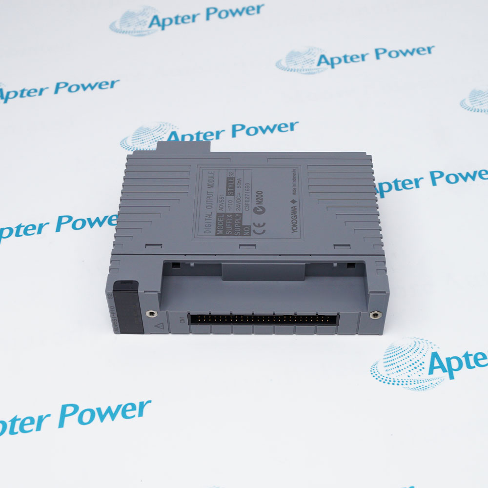
Yokogawa ADV151-P00 S2 brings thirty-two field contact states into a compatible FIO node while separating the input side from the system interface.
  • Thirty-two digital inputs are organized as two sixteen-channel common groups.
  • The hardware accepts either sink or source 24 V DC field signaling.
  • Dual-redundant application is supported in the approved FIO architecture.
  • Multiple direct and cabled field-connection forms are documented for ADV151.

The two common groups share a polarity requirement, so field wiring evidence must be retained together with the software channel map. Terminal-block choice, external adapter/cable use and redundant pairing are installation decisions rather than interchangeable module parameters.

Important Notice: Verify the complete ADV151-P00 S2 tag and both common-group polarities before replacement. Do not infer the historical P00 execution from later ADV151-P5x suffix tables.

Yokogawa ADV151-P00 S2 Manuals & Downloads
Yokogawa ADV151-P00 S2 Official Technical Reference Excerpt (PDF)Yokogawa ADV151-P00 S2 Installation & Commissioning Guide (PDF)

The official excerpt documents ADV151 electrical characteristics, physical form and supported connection options. The installation guide organizes channel mapping, common polarity, isolation and witnessed input checks.


Discrete contact acquisitionRead up to 32 isolated 24 V DC ON/OFF field states within the documented electrical thresholds.
Dual-redundant FIO inputApply matched modules where the approved CENTUM project uses redundant ADV151 input hardware.
Pressure-clamp field wiringTerminate directly through the documented ATB5S or ATB5D pressure-clamp architecture.
Remote terminal-board wiringUse the documented ATD5A, AKB331 and compatible external terminal-board path where the installed design requires remote termination.
ADV151-P00 S2 is a thirty-two-channel 24 V DC input module with two common groups. Preserve channel, common, polarity and field-connection evidence during service.
1
Read the complete ADV151-P00 S2 component tag and record the node, slot and redundant partner before removal.
2
Place every affected digital input in the approved maintenance state and isolate hazardous external 24 V DC circuits.
3
Record the complete channel map for inputs 1-32 and the two common groups before disconnecting field wiring.
4
Keep the externally supplied 24 V DC polarity identical for the channel 1-16 and channel 17-32 common groups.
5
Do not exceed the documented 30.0 V DC maximum input voltage or apply output-module specifications to this input module.
6
Preserve the installed field-connection form, including direct pressure-clamp terminals or the ATD5A and AKB331 cable path.
7
If the application is redundant, label each module and common group so the two sides cannot be exchanged during restoration.
8
After restoration, verify OFF and ON states for permitted test points, node diagnostics, common polarity and redundant behavior before release.

Technical notes

ADV151 receives 32 channels of 24 V DC ON/OFF input. Keep all externally supplied 24 V DC signals within each documented common group at the same polarity. Preserve the complete ADV151-P00 S2 tag because the exact historical P00/S2 execution is not reinterpreted from later P5x ordering tables.

FAQ View All FAQ

  • What input function does Yokogawa ADV151-P00 S2 provide?
    Yokogawa ADV151-P00 S2 receives 32 channels of isolated 24 V DC ON/OFF digital input signals.
  • Can Yokogawa ADV151-P00 S2 accept sink and source inputs?
    Yes. The ADV151 family is rated for 24 V DC sink or source input, subject to the documented common-group polarity rule.
  • Which ON and OFF thresholds apply to Yokogawa ADV151-P00 S2?
    The documented input ON range is 18 to 26.4 V DC, while 5.0 V DC or less is the OFF range.
  • How are channels grouped on Yokogawa ADV151-P00 S2?
    The 32 inputs are divided into two 16-channel common groups: channels 1-16 and channels 17-32.
  • What polarity rule applies to Yokogawa ADV151-P00 S2?
    The externally supplied 24 V DC connected to the two common groups must use the same polarity.
  • Can Yokogawa ADV151-P00 S2 be used redundantly?
    The ADV151 module family supports dual-redundant configuration when installed in compatible FIO hardware and restored according to the approved project design.
  • Which field connection forms support Yokogawa ADV151-P00 S2?
    Published options include ATB5S single or ATB5D dual pressure-clamp terminals, and an ATD5A adapter with AKB331 cable for external terminal-board connections.
  • Which identity must be verified before ordering Yokogawa ADV151-P00 S2?
    Verify the complete ADV151-P00 S2 component tag, original node and slot, connection form, channel commons, polarity and redundancy design. Do not translate P00 from a later P5x ordering table.
Related reading

Related cases and sourcing guidance

View all case studies
Manufacturers

Product Browsing History

Revisit the products you recently viewed on Apter Power.
SPEAK TO OUR TEAM
Let’s find the right solution for you.
Send us the part number, quantity and delivery destination. Our team will help confirm availability and lead time.
  • Whatsapp: +86 18030235313

    Send us a message.
  • sales13@apterpower.com

    Complete our online form.
  • +86 18030235313

    Speak to our team in your native language.