-
Match the complete marking
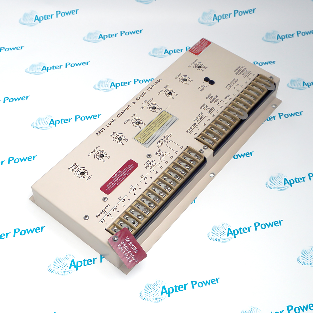
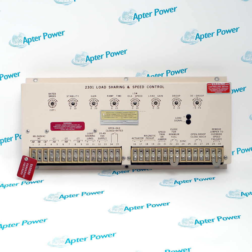
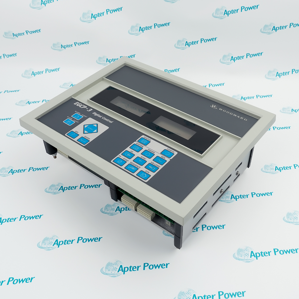
Record the complete 8271-467 marking and any assembly or revision identifier visible on the control unit. Use that identity in the enquiry and quotation.
-
Check the offered item before ordering
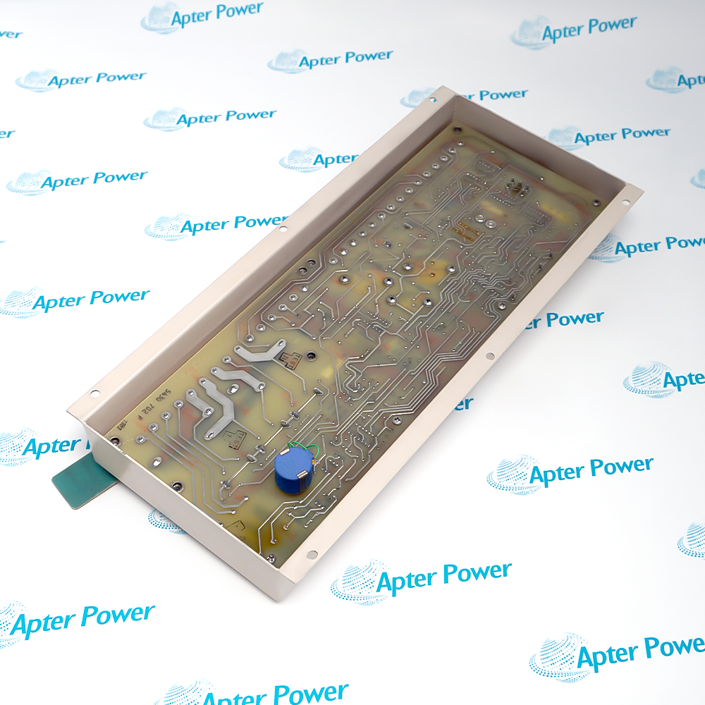
Request available unit label and terminal-connector photos. Have your maintenance team compare the offered 8271-467 with the installed governor equipment and applicable Woodward documentation.
Technical specifications for 8271-467
-
Manufacturer:WOODWARD
-
Product Category:General Automation
-
Spare Part Number:8271-467
-
Weight:1.88 kg
-
Tariff Code:8537101190
-
Power terminals:12 (+), 13 (−) in Woodward test procedure
-
Supply marking:20–40 V DC at terminals 12–13 (newer-control variant)
-
Selector terminal:25 in internal-diode arrangement
-
CT input pairs:4–5, 6–7, 8–9 in bench test
-
CT burden:≤0.30 Ω per pair in bench pre-check
-
Magnetic pickup:18–19; approximately 200 Ω in bench check
-
Bench jumpers:20–21, 26–27, 29–30
-
Load-signal baseline:0 V at full counterclockwise LOAD GAIN
Information
- The controller combines speed regulation with generator load-sharing functions. Its role depends on the matched actuator, speed pickup, current-transformer inputs, external supply and independent protective shutdown.
Paralleling plan: Record bus connection and each unit’s power source
Setting retention: Capture droop, gain, stability and speed adjustments
Acceptance focus: Use controlled loop tests before prime-mover return
The same guide identifies the newer internal-diode controls by a 20–40 VDC marking at terminals 12 and 13. A battery charging above the allowed range can damage the controller; verify the actual terminal legend and supply under operating and charging conditions before applying power.
Woodward Manual 55011 Appendix 3 names 8271-467 among the 2301 models in its portable speed-loop-tester procedure. It gives checks for the CT burden paths, magnetic-pickup transformer, load signal, droop and actuator response. These are controlled bench-test steps, not a replacement for the installed plant drawing or engine-start safety procedure.
-
Woodward Electronic Control Installation Guide excerpt
Woodward Manual 25070 Rev. D - selected original pages, PDF, 8 pages. Installation precautions, wiring and the 8271-467 selector-diode entry. -
Woodward 8271-467 commissioning guide
Prepared by Apter Power - PDF, 2 pages. Identification, installation checks, commissioning and fault isolation.
Application scope: Use only where the prime mover, generator, actuator and protective scheme are engineered for the matching 2301 control and site wiring.
-
Generator load sharing
Coordinate multiple 2301 controls through the documented paralleling lines and common-return power arrangement. -
Prime-mover speed control
Use magnetic-pickup feedback and the matched actuator to regulate the machine within site-approved speed settings. -
Controlled service replacement
Retain the original CT wiring, terminal map, actuator polarity and setting record when exchanging the exact 8271-467 unit. -
Workshop functional verification
Use the Woodward 55011 Appendix 3 procedure with the approved portable speed-loop tester before field installation.
An engine or turbine requires a separate overspeed shutdown device; the governor controller is not that protective device.
Isolate power and trace every CT, pickup, actuator and paralleling connection against the actual installation before moving conductors.
Compare the actual 12–13 terminal legend and worst-case battery-charger voltage with the allowed 20–40 VDC newer-control range.
In the internal-diode high-voltage-selector scheme, disconnect terminal 25 as well as positive and negative power when isolating a control.
Route shielded control wiring away from high-current cables and terminate shields according to the plant drawing and Woodward installation guide.
Use an approved test and emergency-shutdown plan; verify gain, stability, droop and actuator direction before returning the prime mover to service.
Alternative Names
Technical notes
Installation relationship: The 2301 control requires matched pickup, CT load-sensor, actuator and paralleling circuits with separate overspeed protection.
Selector boundary: 8271-467 is listed among controls with an internal selector diode; terminal 25 follows the Woodward figure 5 scheme.
Technical reference: Woodward Electronic Control Installation Guide, Manual 25070 Rev. D, pp. 9–10, and Portable Speed Loop Tester, Manual 55011 Rev. J, Appendix 3.

FAQ View All FAQ
-
Why does Woodward 8271-467 appear in the internal-diode control list?Manual 25070 Table 1 lists the exact 8271-467 code among 2301 controls with an internal diode for the high-voltage-selector scheme. Compare the installed terminal legend and figure 5 wiring before altering a paralleling circuit.
-
How should a high-voltage-selector circuit be isolated around 8271-467?The Woodward guide says to switch terminal 25 together with the positive and negative power input in the internal-diode arrangement. Use the approved plant schematic and lockout sequence; opening only the supply pair may leave an unintended path.
-
What supply check matters before energizing 8271-467?Read the 12–13 terminal marking and measure the supply at normal and charging extremes. Manual 25070 identifies newer internal-diode controls with a 20–40 VDC legend and warns that a 36 V battery charged to 42 V can damage such a control.
-
How are the 8271-467 load-sensor CT inputs pre-checked?Woodward Manual 55011 Appendix 3 specifies resistance checks across terminal pairs 4–5, 6–7 and 8–9, each no greater than 0.30 Ω in the bench-test setup. Isolate and follow the complete procedure before measuring.
-
What does the 8271-467 magnetic-pickup pre-check measure?In the cited 2301 bench procedure, terminals 18–19 should read approximately 200 Ω across the pickup isolation-transformer primary. A field fault still requires checking pickup wiring and the actual machine drawing.
-
Why should 8271-467 load-sharing lines be reviewed before a replacement?Woodward explains that mixed 2301 generations, excessive contact resistance or long paralleling leads can unbalance steady-state sharing. Retain each unit’s connection and switching arrangement from the plant drawing.
-
Which 8271-467 setting records are important for commissioning?Document the pre-work RATED SPEED, GAIN, STABILITY, DE-DROOP, DROOP, LOW IDLE SPEED and RAMP TIME settings. Restore and test them under a controlled procedure rather than copying a bench-test example as the plant setpoint.
-
What closes a Woodward 8271-467 service exchange?Verify control power, pickup and CT signals, actuator response and load-sharing behavior using approved site tests. Prove the separate overspeed shutdown and record all as-left settings before normal operation.
Supporting new and legacy automation
-
Please try to be as accurate as possible with your search.
-
We can quote you on 1000s of specialist parts, even if they are not listed on our website.
-
We can't find any results for “”.
Related cases and sourcing guidance
View all case studiesYou May Also Like
Product Browsing History
-
Whatsapp: +86 18030235313
Send us a message. -
sales13@apterpower.com
Complete our online form. -
+86 18030235313
Speak to our team in your native language.