Get a quick price for 6ES7195-7HF80-0XA0
For more information on how your data is processed and stored by Apterpower please read our privacy policy
Technical specifications for 6ES7195-7HF80-0XA0
-
Manufacturer:Siemens
-
Product Category:PLC Systems
-
Spare Part Number:6ES7195-7HF80-0XA0
-
Estimated shipping dimensions:9.5x9.3x6cm
-
Weight:0.12 kg
-
Tariff Code:8537101190
-
Counliy of origin:Germany
-
Product designation:BM DP/PA / BM FDC
-
System family:SIMATIC ET200M
-
Assembly use:DP/PA Link / FF Link
-
Module function:Coupler bus-module mounting and backplane arrangement
-
Installation rail:Rail for module replacement during operation
-
Adjacent module connection:Mated bus-module connections
-
Module insertion guide:Lateral bus-module guides
-
Horizontal operating ambient:-25 to +60 C
-
Vertical operating ambient:-25 to +40 C
-
Storage / transport temperature:-40 to +70 C
-
Relative humidity:10-95%, without condensation
-
Assembled link protection:IP20
-
Assembled link protection class:Class I; grounding connection to rail
-
Use environment:Fixed, sheltered location
-
Mounting orientation:Horizontal or vertical
-
Assembly removal isolation:Switch off the link's 24 V DC power supplies
Information
Overview
Manuals
Common Applications
Product Precautions
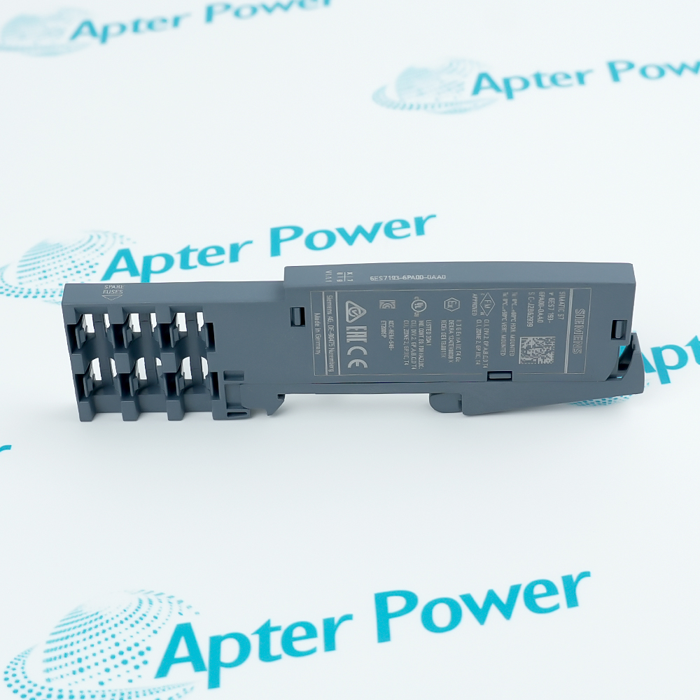
Siemens 6ES7195-7HF80-0XA0 is the BM DP/PA bus module for ET200M installations with an extended temperature range. Identified as BM FDC in the FF Link assembly, the module supports the coupler insertion-and-removal arrangement on the appropriate active-module rail.
- Forms the coupler position in an active bus-module assembly
- Uses the rail intended for module replacement during operation
- Mates with adjacent bus-module connections
- Retains separate horizontal and vertical ambient limits
In an FF Link assembly, BM FDC provides the bus-module position for FDC 157 alongside the interface-module bus arrangement. A redundant IM 153-2 FF master arrangement can still use one FDC 157; a redundant coupler pair instead requires the different BM FDC/FDC unit.
Important Notice: Keep 7HF80 distinct from the 7HG80 redundant-pair bus module. Coupler transfer rates, field-device capacity, supply current and diagnostic LEDs are not standalone BM FDC ratings.
Siemens 6ES7195-7HF80-0XA0 Manuals & Downloads
Siemens 6ES7195-7HF80-0XA0 Technical Reference (PDF)Siemens 6ES7195-7HF80-0XA0 Manufacturer Manual Excerpt (PDF)
The technical reference separates the BM FDC role, installation arrangement and environmental limits. The manufacturer manual excerpt retains 22 unchanged original FF Link pages covering scope, mounting, operating conditions and order numbers; it is not the complete manual.

Single-coupler FF Link
Provides the bus-module position for a single FDC 157 in the active-module installation arrangement.
ET200M DP/PA Link
Supports the BM DP/PA position in the ET200M fieldbus-link assembly.
Interface-master redundancy
Can be used with a single coupler where the IM 153-2 FF interface masters are redundant; this is not coupler-pair redundancy.
Configured module replacement
Supports the documented insertion-and-removal arrangement when the link, rail and adjacent modules are configured for that function.
Verify Siemens 6ES7195-7HF80-0XA0 as BM FDC and identify the installed interface-master and coupler arrangement before modifying the assembly.
1
Distinguish a single FDC position from a redundant FDC pair before choosing the bus module.
2
Use the mounting rail intended for module replacement during operation.
3
Switch off the link's 24 V DC power supplies before dismantling the bus assembly.
4
Position the bus module on the rail and engage its rail connection.
5
Slide the adjacent bus modules together until their connections mate.
6
Insert the coupler using the bus module's lateral guides.
7
Tighten the module screws to secure the modules and bus assembly to the rail.
8
Restore the assembled link and verify its configured operation within the mounting-specific ambient limit.
Technical notes
Use the rail intended for module replacement during operation and mate adjacent bus-module connections before securing the coupler. BM FDC is distinct from the BM FDC/FDC unit used for a redundant coupler pair; switch off the link's 24 V DC supplies before dismantling the bus assembly.
FAQ View All FAQ
-
Does the 7HF80 bus module accommodate the redundant FDC pair?The BM FDC designation is separate from BM FDC/FDC (redundant), whose order number ends in 7HG80-0XA0. Use the paired module for the documented redundant coupler arrangement rather than treating these two bus modules as interchangeable.
-
Can redundant interface masters still operate with one FDC on BM FDC?Yes. The FF Link master-redundancy arrangement can use two IM 153-2 FF modules with one FDC 157. Redundancy of the interface masters does not by itself mean the couplers form a redundant pair.
-
Why is the standard S7 rail not the active-module mounting choice?The installation with active bus modules uses the rail intended for hot-swapping modules. A standard configuration instead connects the modules with the supplied bus connector; that is a different mounting arrangement.
-
Does the insertion-and-removal function allow dismantling the bus assembly live?No such permission follows from that function. The dismantling procedure requires switching off the link's 24 V DC power supplies first. Distinguish replacing a configured front module from removing the underlying bus assembly.
-
What has to engage before the FDC is secured?The adjacent bus modules are slid together so their connections mate. The FDC is inserted using the lateral guides, then the module screws are tightened to fix the assembly to the rail.
-
What changes if the installed link sees continuous rather than occasional vibration?For 10-58 Hz, the continuous amplitude limit is 0.0375 mm, compared with 0.075 mm for infrequent exposure. For 58-150 Hz, the corresponding accelerations are 0.5 g and 1 g. Reduce excessive vibration with appropriate installation measures instead of applying the infrequent limit continuously.
-
Does IP20 make an exposed link assembly suitable for wet locations?IP20 does not protect against water penetration. The link components are open equipment for a suitable restricted-access enclosure or electrical service room; humidity is specified without condensation.
-
Should the FDC's field-device capacity or transmission rate be entered as BM FDC specifications?Those values describe the coupler or the complete fieldbus link, not the BM FDC mounting/backplane unit. Keep the bus-module role separate from the communication and power ratings of the installed FDC.
Manufacturers
Supporting new and legacy automation
Whether you're maintaining existing equipment or sourcing parts for current systems, we provide fast, dependable supply you can rely on.
-
Please try to be as accurate as possible with your search.
-
We can quote you on 1000s of specialist parts, even if they are not listed on our website.
-
We can't find any results for “”.
PRODUCTS IN SEARCH PAGE ()
50+ account managers available now
Related reading
Related cases and sourcing guidance
View all case studies
Manufacturers
You May Also Like
Explore related automation components available through Apter Power.
Manufacturers
Product Browsing History
Revisit the products you recently viewed on Apter Power.
SPEAK TO OUR TEAM
Let’s find the right solution for you.
Send us the part number, quantity and delivery destination. Our team will help confirm availability and lead time.
-
Whatsapp: +86 18030235313
Send us a message. -
sales13@apterpower.com
Complete our online form. -
+86 18030235313
Speak to our team in your native language.