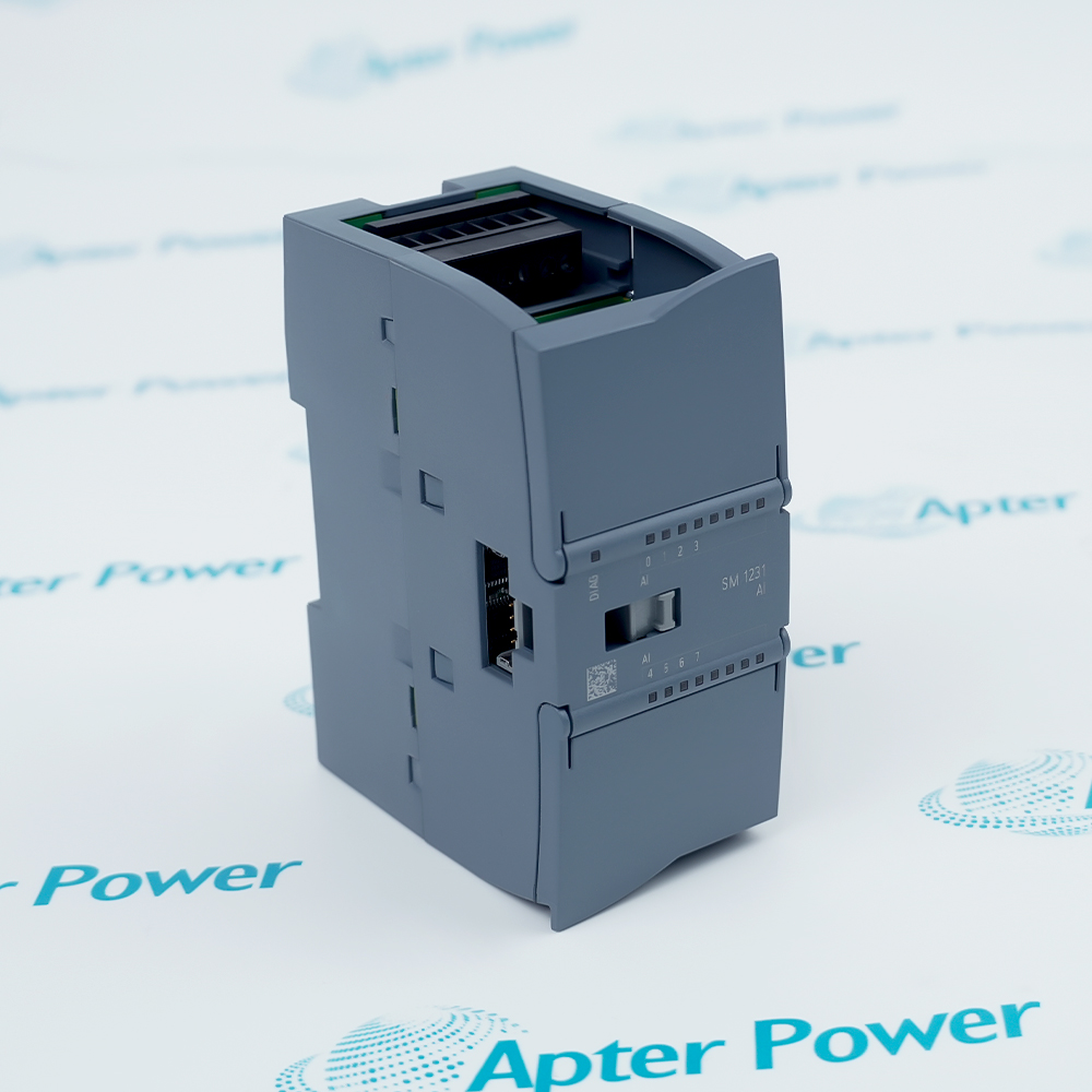
-
Match the complete marking
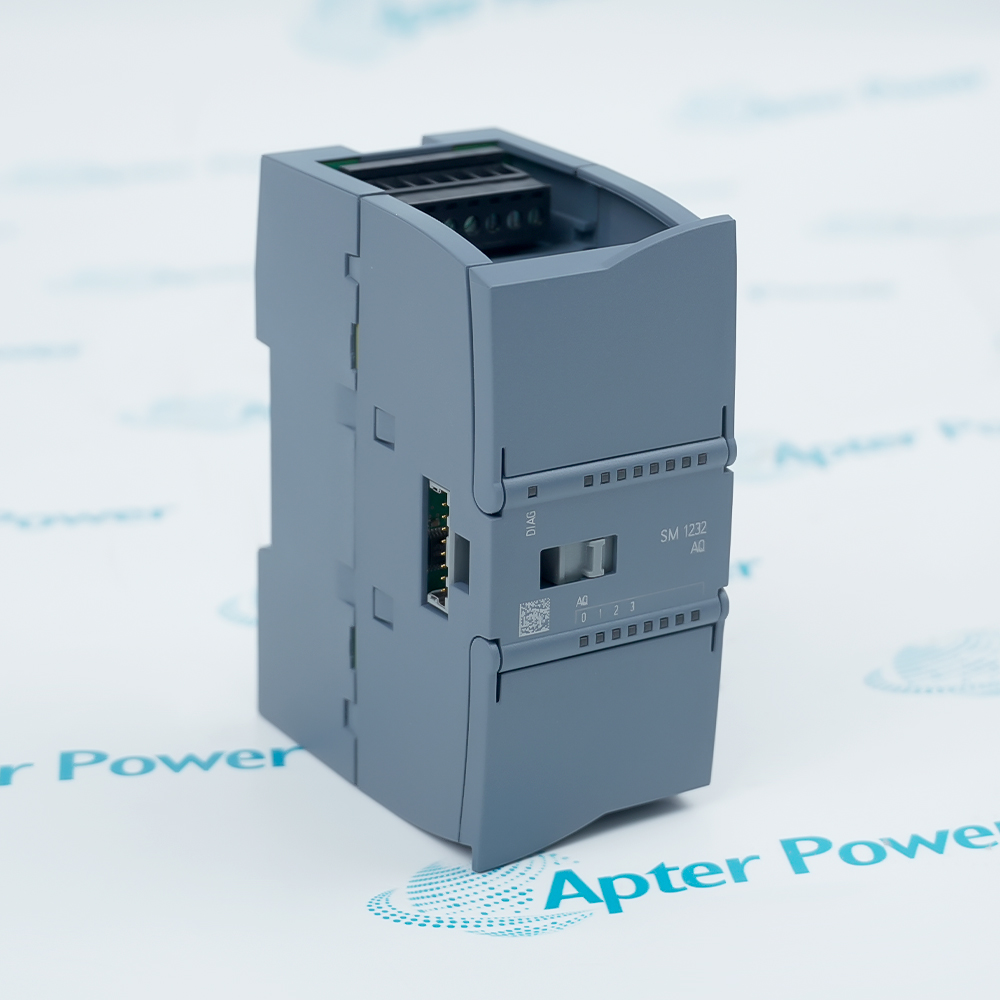
Provide the complete Siemens 6ES7232-4HD32-0XB0 marking.
-
Check the offered item before ordering
Request available label and connector photos. Have your maintenance team compare the offered 6ES7232-4HD32-0XB0 with the installed equipment and applicable Siemens instructions.
Technical specifications for 6ES7232-4HD32-0XB0
-
Manufacturer:Siemens
-
Product Category:PLC Systems
-
Spare Part Number:6ES7232-4HD32-0XB0
-
Weight:0.2 kg
-
Tariff Code:8537101190
-
Analog outputs:4
-
Output ranges:±10 V, 0–20 mA, 4–20 mA
-
Voltage resolution:14 bits
-
Current resolution:13 bits
-
Voltage load:≥1000 Ω
-
Current load:≤600 Ω
-
Accuracy at 25 °C:±0.3% of full scale
-
Accuracy over -20 to +60 °C:±0.6% of full scale
-
Bus current consumption:80 mA
-
24 V consumption without load:45 mA
-
Power dissipation:2.0 W
-
Maximum signal cable:100 m, twisted and shielded
Information
- Siemens 6ES7232-4HD32-0XB0 translates controller setpoints into four field analog signals with mode-specific resolution, load limits and diagnostic behavior.
Output coordination: Channel range and receiving-device scaling must describe the same command.
State handling: Retained or substitute outputs define behavior when the controller changes operating state.
Channel connections share the module's reference arrangement. Designing separate process loops therefore requires attention to common returns as well as to the receiving devices.
Controller state changes can retain a command or substitute a configured value. That behavior forms part of the process operating strategy and must be selected deliberately for the connected actuators.
6ES7232-4HD32-0XB0 Official Technical Excerpt
Siemens 6ES7232-4HD32-0XB0: original manufacturer technical information covering the specified interfaces and operating limits. PDF · 4 pages.6ES7232-4HD32-0XB0 Installation & Verification Guide
Apter Power guide covering output assignments, load and references, scaling and stop, supply and signal, actuator release. PDF · 5 pages.
Application boundary: Common-reference wiring and controller STOP behavior are part of the process design, not independent accessories.
Valve and actuator setpoints
Configured current or voltage signals command compatible field devices.Drive reference signals
Analog setpoints connect an S7-1200 application to a receiving drive input.Process signal simulation
Controlled output values support commissioning checks with the process secured.Defined STOP behavior
Per-channel substitute or retained values support the engineered response to CPU state changes.
Place connected valves, drives or other receivers in their approved maintenance state. Review the CPU STOP and power-loss response so an output interruption or default zero value cannot cause an unintended process action.
Trace each output and its return conductor, including channels 2 and 3 on X13. Account for the absence of galvanic isolation when reviewing common references and grounding.
Restore the intended last-value or substitute-value behavior for every output. Review the default zero value against the process requirements instead of accepting it automatically after a configuration download.
With actuators secured, command low, intermediate and high reference values and measure the resulting signal. Compare the receiving indication as well as the module terminals to detect wiring or scaling discrepancies.
Record the range, load assessment, STOP behavior and measured output checks. Remove temporary test equipment and overrides before returning the receiving devices to normal process control.
Test the required mode-specific fault response under the approved procedure. Confirm the controller and operator indication, and restore the normal circuit after testing current wire-break or voltage short-related behavior.
Alternative Names
Technical notes
Operating boundary: Voltage and current outputs have different resolution and load limits.
Integration details: Restore mode, scaling, common references and STOP behavior before enabling actuators.

FAQ View All FAQ
-
Why can a correct raw command produce the wrong actuator position with 6ES7232-4HD32-0XB0?The selected voltage/current range and the receiver's scaling may differ. Compare low, intermediate and high commands at both the terminals and the receiving device.
-
How does a high loop load affect current output from 6ES7232-4HD32-0XB0?The module must drive the commanded current through the entire loop burden. Check cable and receiver loading when the output fails to follow the command, rather than changing application scaling first.
-
Why is retaining the last output on STOP not automatically the safest setting for 6ES7232-4HD32-0XB0?A held command can keep an actuator energized, while a substitute value can also cause movement. Select and validate the state that suits the process instead of assuming either behavior is universally safe.
-
Can settling time alone define the application update rate of 6ES7232-4HD32-0XB0?No. It describes output response under a stated load. CPU updates, communication and receiver response also contribute to the effective control timing.
-
What changes when a capacitive load is connected to 6ES7232-4HD32-0XB0?Settling behavior differs from the resistive-load condition. Include the actual receiver and cable characteristics when judging how quickly a commanded voltage becomes usable.
-
Why must channel returns on 6ES7232-4HD32-0XB0 be reviewed together?The channels are not galvanically isolated from one another. Check common references and grounding so separate field loops do not create an unintended electrical interaction.
-
How should mode-specific diagnostics be tested on 6ES7232-4HD32-0XB0?Use the fault condition applicable to the configured current or voltage mode and verify the controller indication. A test valid for one mode does not demonstrate every diagnostic in another.
-
Why should the field supply be assessed separately from PLC recognition of 6ES7232-4HD32-0XB0?Recognition through the backplane does not prove that the analog field circuit has its required supply and load conditions. Check both domains before diagnosing the output electronics.
Supporting new and legacy automation
-
Please try to be as accurate as possible with your search.
-
We can quote you on 1000s of specialist parts, even if they are not listed on our website.
-
We can't find any results for “”.
Related cases and sourcing guidance
View all case studiesYou May Also Like
Product Browsing History
-
Whatsapp: +86 18030235313
Send us a message. -
sales13@apterpower.com
Complete our online form. -
+86 18030235313
Speak to our team in your native language.