-
Match the complete marking
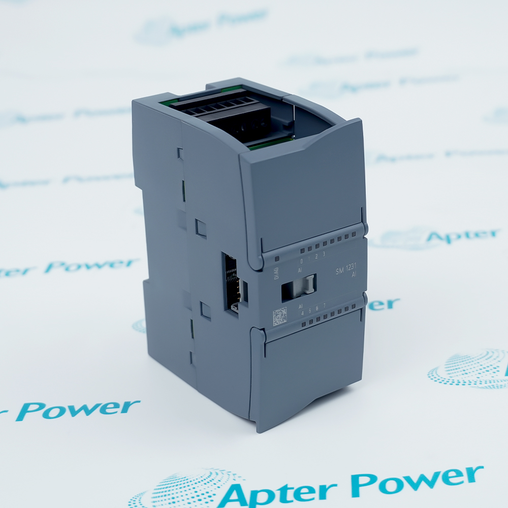
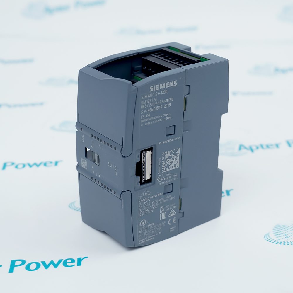
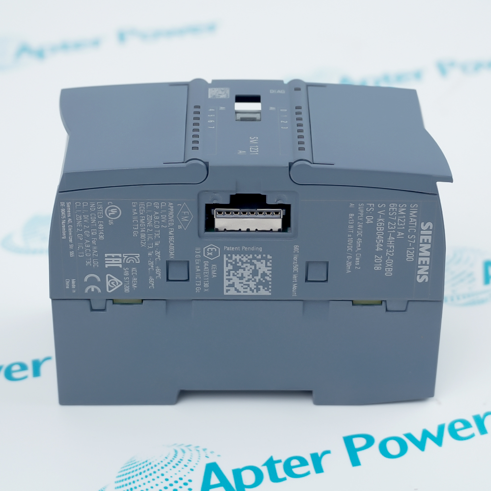
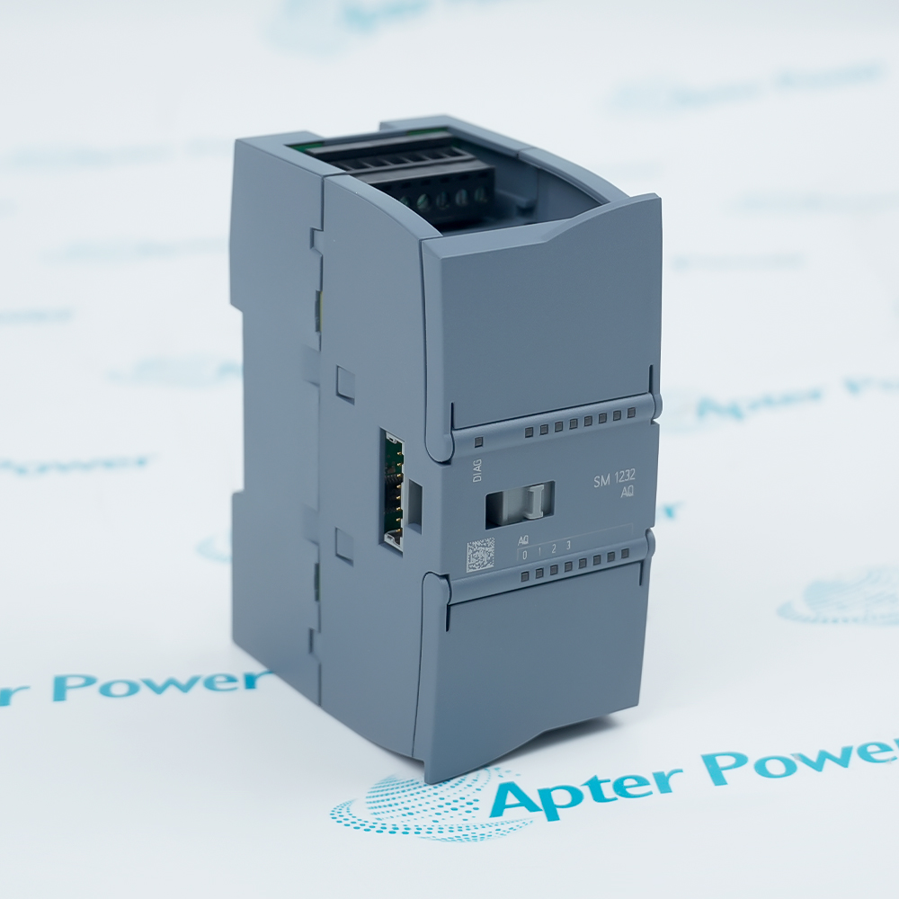
Provide the complete Siemens 6ES7231-4HF32-0XB0 marking. Match 6ES7231-4HF32-0XB0 and the eight-channel terminal arrangement.
-
Check the offered item before ordering
Request available label and connector photos. Have your maintenance team compare the offered 6ES7231-4HF32-0XB0 with the installed equipment and applicable Siemens instructions.
Technical specifications for 6ES7231-4HF32-0XB0
-
Manufacturer:Siemens
-
Product Category:PLC Systems
-
Spare Part Number:6ES7231-4HF32-0XB0
-
Weight:0.18 kg
-
Tariff Code:8537101190
-
Analog inputs:8 differential channels
-
ADC resolution:12 bits plus sign
-
Voltage ranges:±10 V; ±5 V; ±2.5 V
-
Current ranges:0–20 mA; 4–20 mA
-
Module supply:24 V DC nominal
-
Current input resistance:270–290 Ω
-
Voltage destruction limit:35 V
-
Current destruction limit:40 mA
-
Input terminal groups:X10: 0–1; X11: 2–3; X12: 4–5; X13: 6–7
-
Range configuration:Voltage/current selectable in groups of 2
Information
- Siemens 6ES7231-4HF32-0XB0 brings several independent process measurements into an S7-1200 controller without requiring a separate module for every signal.
Ranges: Voltage or current process signals
Conversion: 12 bits plus sign
The terminal arrangement groups channels 0–1 on X10, 2–3 on X11, 4–5 on X12 and 6–7 on X13. The module supply uses L+ and M, with functional earth provided at the designated connection. Similar-looking input pairs still belong to different process channels.
The 13-bit ADC representation includes the sign bit. Channel filtering and interference rejection affect response time, so a raw conversion figure alone does not define the complete measurement delay. Scaling and diagnostic handling belong in the controller application.
6ES7231-4HF32-0XB0 Official Technical Excerpt
Siemens 6ES7231-4HF32-0XB0: original manufacturer technical information covering the specified interfaces and operating limits. PDF · 6 pages.6ES7231-4HF32-0XB0 Installation & Verification Guide
Apter Power installation and verification guide covering map the eight measurements, trace the connector groups, evaluate current-loop loading, inject a controlled voltage, check channel identity in the plc. PDF · 5 pages.
Application scope: The applications below describe its technical role. Select associated hardware and configuration for the actual installation.
Mixed process measurement
Acquire supported voltage and current signals in an S7-1200 analog input station.Bipolar signal acquisition
Measure signed ±2.5 V, ±5 V or ±10 V signals with the matching channel configuration.Current-transmitter loops
Read 0–20 mA or 4–20 mA transmitters after checking loop burden and power.Multi-channel verification
Use the four connector groups to organize an eight-point measurement and calibration plan.
Set the voltage or current range to the actual transmitter output. Check bipolar polarity and the distinction between 0–20 mA and 4–20 mA before calibration.
Check L+, M and the designated functional-earth connection against the approved wiring. Keep supply conductors distinct from measurement inputs.
Retain the approved interference-rejection and smoothing settings. Evaluate measurement delay with the actual process rather than choosing maximum filtering automatically.
For a current channel, test the configured low and high values and an intermediate value. Keep the signal within the supported range and observe application diagnostics.
Save the channel map, hardware ranges, filter settings, scaling and calibration results. Release each loop only after the input value and diagnostic handling match the intended process.
Confirm that each injected input changes only its assigned process variable. Investigate swapped connectors or application addresses before accepting the measured accuracy.
Alternative Names
Technical notes
Operating boundary: The ± range selection and signed representation must agree with the engineering-unit conversion in the PLC. A valid raw value is not proof of correct process scaling.
Integration details: Preserve the full 4HF32 order number, connector/channel mapping, range settings and filter configuration; do not substitute data from a newer G2 module.
Technical basis: Siemens S7-1200 Programmable Controller System Manual, V4.6, A5E02486680-AP. The SM 1231 AI 8 × 13-bit column applies to 6ES7231-4HF32-0XB0. Range, filtering and wiring conditions determine the usable channel response.

FAQ View All FAQ
-
Can 6ES7231-4HF32-0XB0 measure a bipolar ±2.5 V transducer?Yes. ±2.5 V is one of its selectable voltage ranges, alongside ±5 V and ±10 V.
-
How are eight inputs distributed across the connectors of 6ES7231-4HF32-0XB0?X10 carries channels 0 and 1, X11 carries 2 and 3, X12 carries 4 and 5, and X13 carries 6 and 7.
-
Does the 13-bit specification of 6ES7231-4HF32-0XB0 include a sign bit?Yes. It is 12 bits plus sign, which should be considered when interpreting signed analog values.
-
Why must the configured range of 6ES7231-4HF32-0XB0 match a 4–20 mA transmitter?The current range defines the measurement scaling and diagnostic interpretation. A voltage or 0–20 mA configuration changes the meaning of the same input condition.
-
Can a 35 V signal be used as a normal measurement input on 6ES7231-4HF32-0XB0?No. The destruction limit is not a measurement range. Use only the configured supported voltage range for normal operation.
-
Can the eight inputs of 6ES7231-4HF32-0XB0 be configured independently for voltage and current?Voltage/current selection is made in groups of two. Plan each pair together rather than assuming eight independently selectable input modes.
-
What does differential input mean for wiring 6ES7231-4HF32-0XB0?Each channel uses its assigned positive and negative input terminals. Keep the paired conductors together and maintain the permitted common-mode conditions.
-
Why should 6ES7231-4HF32-0XB0 be tested at more than one calibration point?Low, mid and high inputs reveal scaling, polarity or range errors that a single reading can conceal. Check the resulting engineering values in the controller as well as the electrical input.
Supporting new and legacy automation
-
Please try to be as accurate as possible with your search.
-
We can quote you on 1000s of specialist parts, even if they are not listed on our website.
-
We can't find any results for “”.
Related cases and sourcing guidance
View all case studiesYou May Also Like
Product Browsing History
-
Whatsapp: +86 18030235313
Send us a message. -
sales13@apterpower.com
Complete our online form. -
+86 18030235313
Speak to our team in your native language.