Speak to a sourcing specialist
sales13@apterpower.com

6DD1606-4AB0

I/O Expansion Module
In Stock
Ships by Saturday, November 7
Fast Shipping Available
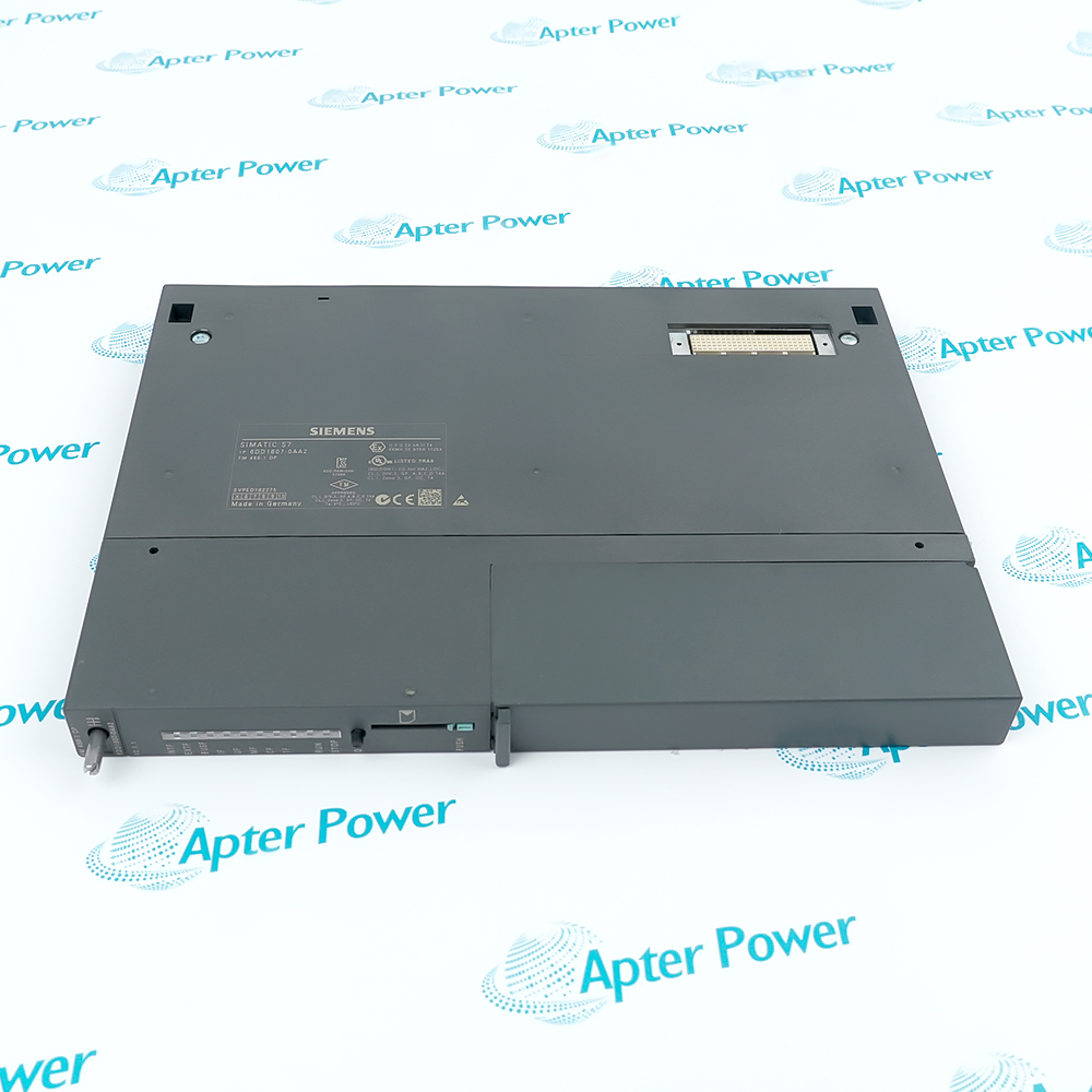
Product image is representative; revision or series may vary. Contact us to request a specific version.

Product Describe:

Siemens 6DD1606-4AB0 is the IT42 analog and binary I/O expansion module for SIMADYN D PM5/PM6 CPU assemblies. It combines integrating voltage/frequency-conversion inputs, sampled analog inputs, analog outputs and binary I/O through separate X6, X7 and X8 interfaces.

Get a quick price for 6DD1606-4AB0
E-mail *
Mobile *
Company
Content *
Quantity *
Upload (gif, jpg, jpeg, png, bmp, doc, docx, xls, xlsx, ppt, pdf, csv)
For more information on how your data is processed and stored by Apterpower please read our privacy policy

What happens after you enquire

  • 1

    Requirement review

    We review the part number, quantity and delivery requirements and ask for any missing details.
  • 2

    Quotation and availability

    We confirm the proposed item, condition, availability, price and estimated lead time in the quotation.
  • 3

    Order confirmation and dispatch

    Once the quotation and purchasing details are agreed, your contact will coordinate the order and available dispatch information.

Technical specifications for 6DD1606-4AB0

  • Manufacturer:
    Siemens
  • Product Category:
    PLC Systems
  • Spare Part Number:
    6DD1606-4AB0
  • Estimated shipping dimensions:
    2.8×25.3×26.1cm
  • Weight:
    0.4 kg
  • Tariff Code:
    8537101190
  • Counliy of origin:
    Germany
  • Module designation:
    IT42
  • Supported CPU modules:
    PM5 / PM6
  • Maximum ITxx expansion modules per CPU:
    2
  • Additional slots occupied by IT42:
    1
  • Integrating analog inputs:
    4 differential, floating, voltage/frequency conversion
  • Integrating input range:
    -10 to +10 V
  • Integrating input resistance:
    470 kohm
  • Integrating input filter cutoff:
    2 kHz at -3 dB
  • Integrating resolution at 1 ms:
    13 bits
  • Integrating resolution at 4 ms:
    15 bits
  • Integrating resolution at 20 ms:
    17 bits
  • Integrating relative accuracy:
    Typically 14 bits
  • Integration time control:
    AFC block sampling time or interval between positive trigger edges
  • External trigger inputs:
    4
  • Sampled analog inputs:
    4 differential, non-floating
  • Sampled input range:
    -10 to +10 V
  • Sampled input resistance:
    470 kohm
  • Sampled input filter cutoff:
    1.5 kHz at -3 dB
  • Sampled input resolution:
    12 bits
  • Sampled absolute accuracy:
    Typically 10 bits over full temperature range
  • Maximum sampled conversion time:
    45 microseconds
  • Analog outputs:
    4, non-floating, associated ground
  • Analog output range:
    -10 to +10 V
  • Analog output current:
    +/-10 mA
  • Analog output resolution:
    16 bits
  • Analog output monotonicity:
    14 bits over full temperature range
  • Analog output absolute accuracy:
    Typically 13 bits over full temperature range
  • Analog output short-circuit protection:
    To ground
  • Binary inputs:
    16, non-floating
  • Binary input rated voltage:
    24 V DC
  • Binary input logic 0:
    -1 to +6 V or open circuit
  • Binary input logic 1:
    +13 to +33 V
  • Binary input logic 1 current:
    Typically 3 mA
  • Binary input delay at 24 V:
    50 microseconds
  • Binary outputs:
    16, non-floating
  • Binary output external supply:
    24 V DC nominal; +20 to +30 V including ripple
  • Brief external supply limit:
    +35 V for maximum 0.5 s
  • Binary output current per channel:
    50 mA nominal and maximum
  • Binary output short-circuit protection:
    Electronic and thermal
  • Binary output logic 0 level:
    Maximum 3 V
  • Binary output logic 1 level:
    Supply voltage minus 2.5 V
  • Binary output residual current:
    20 microA at logic 0
  • Maximum binary switching delay:
    15 microseconds
  • Inductive switch-off voltage limit:
    Supply voltage plus 1 V
  • X6 connector:
    15-pin sub-D; integrating analog inputs
  • X7 connector:
    25-pin sub-D; sampled inputs and analog outputs
  • X8 connector:
    50-pin sub-D; binary I/O and trigger inputs
  • X6 cable and interface:
    SC50 / SU10
  • X7 cable and interface:
    SC51 / SU10
  • X8 direct-terminal cable:
    SC49 / two SU10 interfaces
  • X8 segmented-interface cable:
    SC54 / matched SB10, SB60, SB61, SB70, SB71 or SU12 interfaces
  • +5 V supply range:
    +4.75 to +5.25 V
  • +5 V typical current drain:
    420 mA
  • +15 V supply range:
    +14.4 to +15.6 V
  • +15 V typical current drain:
    450 mA
  • -15 V supply range:
    -15.6 to -14.4 V
  • -15 V typical current drain:
    140 mA
  • External 24 V current drain:
    100 mA plus binary output currents
  • System air-intake temperature:
    0 to +55 C
  • System storage temperature:
    -25 to +70 C

Information

Overview Manuals Common Applications Product Precautions
Siemens 6DD1606-4AB0 is the IT42 analog and binary I/O expansion module for SIMADYN D PM5/PM6 CPU assemblies. It combines integrating voltage/frequency-conversion inputs, sampled analog inputs, analog outputs and binary I/O through separate X6, X7 and X8 interfaces.
  • Combines integrating and sampled acquisition without treating them as one input type
  • Keeps analog, binary and trigger connections in separate interface groups
  • Extends the CPU assembly through the local expansion bus
  • Uses defined cable branches for direct terminals or signal-adapting interfaces

X6 carries the integrating inputs through SC50/SU10, while X7 uses SC51/SU10 for the sampled inputs and analog outputs. X8 combines binary I/O and external integrating-input triggers; SC49 connects two SU10 units, whereas SC54 separates the signal groups into branches that accept only their matching interfaces.

Important Notice: Keep the floating integrating-input group distinct from the non-floating sampled inputs and outputs. Isolate the subrack and applicable external supplies before rebuilding the PM5/PM6 expansion assembly.

Siemens 6DD1606-4AB0 Manuals & Downloads
Siemens 6DD1606-4AB0 Technical Reference (PDF)Siemens 6DD1606-4AB0 Manufacturer Manual Excerpt (PDF)

The technical reference distinguishes the IT42 signal groups, limits and expansion-assembly decisions. The manufacturer excerpt retains 35 unchanged original pages covering source identity, installation/EMC guidelines, system conditions and the complete IT42 section; it is not the full manual.


Time-integrated voltage acquisition
Measures differential signals through voltage/frequency conversion using the AFC sampling interval or externally defined trigger interval.
Sampled analog feedback
Acquires differential voltage signals through the separate ADU input group when the configured application uses sampled rather than integrating acquisition.
Bipolar analog command output
Provides the configured analog voltage commands through X7 and the SC51/SU10 terminal arrangement.
Combined binary and trigger interface
Connects machine binary inputs, binary outputs and the external triggers through the selected X8 cable and branch-specific interface modules.
Identify Siemens 6DD1606-4AB0 as IT42, confirm its position on the PM5/PM6 assembly, and distinguish integrating, sampled and binary signal groups before rewiring.
1
Isolate the CPU/subrack and the external binary-I/O supply before rebuilding the expansion assembly.
2
Handle the expansion board with ESD grounding and conductive work surfaces.
3
Retain the metal distance pieces for the first ITxx board's identification contact.
4
Use the documented plastic spacing arrangement when a second ITxx board is fitted.
5
Keep the SC50/X6 integrating-input connection separate from SC51/X7 analog I/O.
6
Match each SC54 branch to its permitted signal/interface group; do not swap branches arbitrarily.
7
Check the external binary supply and per-channel output load before energization.
8
Verify the configured integration interval, trigger response and each restored signal group during commissioning.

Technical notes

Match SC50, SC51 and the selected X8 cable/interface arrangement to their respective signal groups. The first ITxx expansion board uses metal distance pieces for its identification contact; a second expansion board changes the spacer arrangement, so retain the assembly sequence when replacing IT42.

FAQ View All FAQ

  • Can every IT42 integrating input be treated as a fixed 17-bit channel?
    Its resolution depends on integration time: 13 bits at 1 ms, 15 bits at 4 ms and 17 bits at 20 ms. Select the acquisition interval together with the required response and resolution rather than applying the highest figure to every sampling configuration.
  • How does external triggering define the integrating measurement interval?
    The integrating interval may be the AFC function block sampling time or the time between two positive edges of an external trigger signal. Four trigger inputs are carried at X8, separate from the integrating signal pairs at X6.
  • Are the X6 and X7 analog input groups equally isolated?
    No. X6's integrating inputs are differential and floating with voltage/frequency conversion. The sampled ADU inputs at X7 are differential but non-floating, so their common-reference arrangement cannot be assumed identical.
  • Can the 33 V binary-input logic-high limit be used as a continuous output-supply limit?
    No. The input logic-high range extends to 33 V, but the external binary-output supply is specified at 20-30 V including ripple. A brief 35 V limit applies only for up to 0.5 seconds; it is not a continuous supply rating.
  • Why does the first expansion board require metal distance pieces?
    They establish the electrical contact used to identify the first ITxx expansion board. The second-board assembly uses the different plastic spacing arrangement; retaining only the mechanical separation without the identification contact is not equivalent.
  • Does replacing SC49 with SC54 leave every terminal branch equivalent?
    SC49 connects X8 to two SU10 direct-terminal interfaces. SC54 divides X8 into signal-specific branches, each accepting only the interfaces matching that branch; binary inputs, binary outputs and integrating-input triggers must remain in their assigned groups.
  • Which limits distinguish the sampled inputs from the integrating inputs?
    The sampled group has 12-bit resolution, a 1.5 kHz input filter cutoff and a maximum conversion time of 45 microseconds. The integrating group uses a 2 kHz cutoff and time-dependent resolution, so the two acquisition methods must be parameterized separately.
  • How much current can one binary output switch?
    Each binary output is rated at 50 mA, which is also its maximum value. Output protection is electronic and thermal; include the connected output currents when calculating the external 24 V supply demand rather than using the module's 100 mA base demand alone.
Related reading

Related cases and sourcing guidance

View all case studies
SPEAK TO OUR TEAM
Let’s find the right solution for you.
Send us the part number, quantity and delivery destination. Our team will help confirm availability and lead time.
  • Whatsapp: +86 18030235313

    Send us a message.
  • sales13@apterpower.com

    Complete our online form.
  • +86 18030235313

    Speak to our team in your native language.