-
Match the complete marking
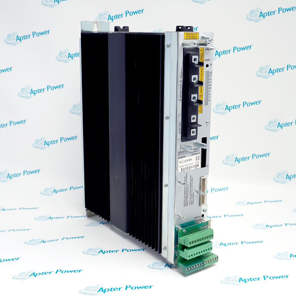
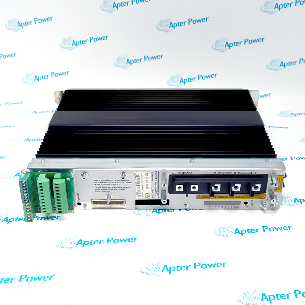
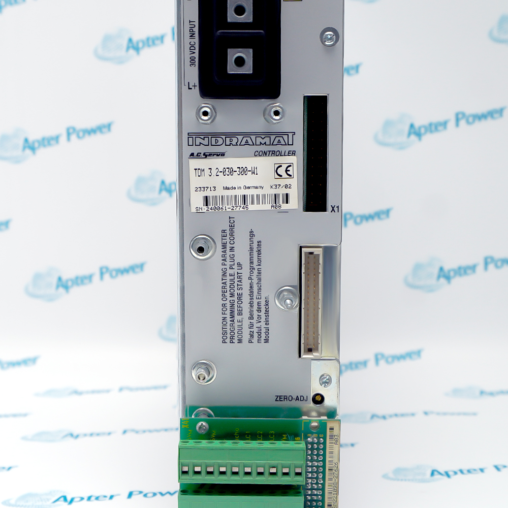
Match the full TDM3.2-030-300-W1 label, DC-link supply, motor/MOD pairing and fan before ordering.
-
Check the offered item before ordering
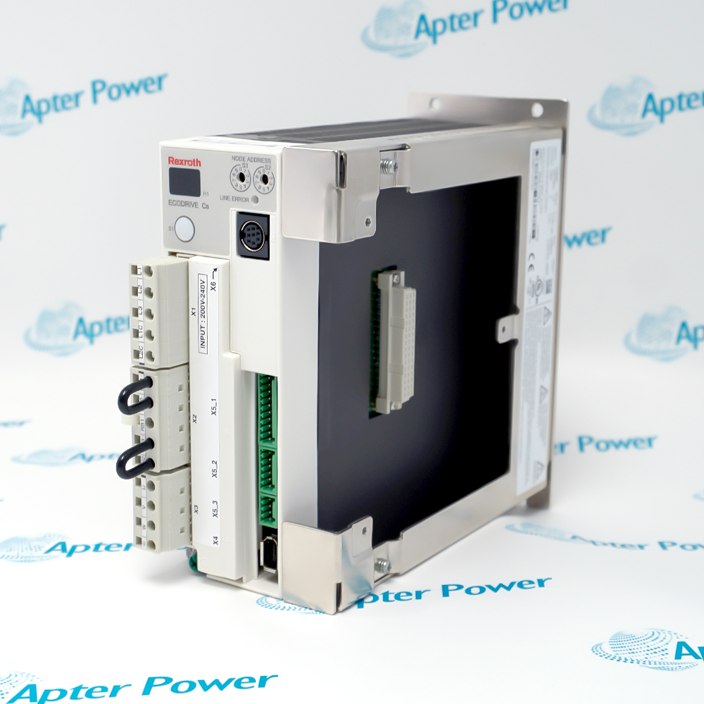
Request photos of the offered TDM3.2-030-300-W1 and have your maintenance team compare them with the installed axis and applicable Indramat MAC Servo Drives documentation before ordering.
Technical specifications for TDM3.2-030-300-W1
-
Manufacturer:Rexroth
-
Product Category:Servo Drives
-
Weight:6.62 kg
-
Tariff Code:8537101190
-
Drive family:TDM 3.2 modular servo drive
-
Full reference:TDM3.2-030-300-W1; forced-ventilated variant
-
Type current:30 A
-
Peak current:30 A
-
Continuous current:25 A
-
DC link voltage:300 V DC ±15%
-
Continuous power:9 kW in the TDM 3 technical table
-
Power loss at continuous current:175 W
-
Cooling:Forced ventilation; one fan unit required
-
MOD module choices:MOD 13 without set-point potentiometer or MOD 14 with one
-
Motor family context:TDM 3 family covers specified MAC 63 to MAC 112B motors
-
Rated ambient:+5 to +45 °C
-
Reduced-rated ambient limit:Up to +55 °C under derating
-
Mounting altitude:Up to 1000 m without rated-data reduction
-
Protection class:IP 10; cabinet installation
Information
- The TDM3.2-030-300-W1 sits in an Indramat modular drive system between the DC-link supply, command inputs and a matched MAC motor. Cooling and programming are essential parts of the drive configuration.
Operating limit: 25 A continuous with forced ventilation
Configuration: Motor-matched MOD 13/14 programming module
The W1 suffix in this TDM 3.2 entry denotes forced ventilation. The manual states that TDM3.2-030-300-W1 may be operated only with one fan unit. It gives +5 to +45 °C for rated data, reduced ratings up to +55 °C and 1000 m altitude without reduction. Confirm the actual fan supply, airflow and cabinet clearance before enabling the axis.
A MOD programming module defines motor-specific operating parameters and command weighting. The manual lists MOD 13 and MOD 14 for the TDM 3.2 class, with a set-point potentiometer distinction; the module label must match the controller and motor. A replacement drive should therefore be reviewed with its MAC motor, feedback cable, supply module, MOD code and serial-dependent diagnostic display, then commissioned under a controlled motion test.
-
TDM3.2-030-300-W1 Technical Reference
Original Indramat manual excerpt · PDF, 9 pages. TDM3.2-030-300-W1 ratings, fan requirement and MAC drive-system context. -
TDM3.2-030-300-W1 Installation & Commissioning Guide
Apter Power guide · PDF, 5 pages. Module marking, fan, MOD code, supply checks, controlled test and handover.
Platform applications: The TDM 3 family is documented with specified MAC 63 to MAC 112B motors; actual motor, MOD and supply compatibility must be checked for the installed axis.
-
Modular MAC servo axis
Match the drive with an approved MAC motor, feedback cable and DC-link supply using the system records. -
Motor-specific parameter reuse
Transfer only a verified MOD programming module whose controller and motor labels match the new drive installation. -
Forced-cooled cabinet retrofit
Provide the specified fan unit and unobstructed airflow, then compare thermal conditions with rated-data limits. -
Faulted drive recovery
Use the actual serial-range diagnostic chart to distinguish controller voltage, feedback, power and temperature faults.
Follow the manual and site lockout procedure, wait for stored energy to discharge and measure the link before touching terminals.
The TDM3.2-030-300-W1 requires forced ventilation; a W0 variant is not equivalent by current alone.
Identify the approved fan type, voltage and airflow. Do not operate the W1 drive with its fan omitted or stopped.
Read the MOD label and verify both controller and MAC motor codes before inserting or energizing it.
Respect clearance and +5 to +45 °C rated range; apply derating if the design permits operation above it.
Verify command, enable, feedback, current and serial-range diagnostics before restoring full machine motion.
Alternative Names
Technical notes
Source scope: Exact TDM3.2-030-300-W1 current, DC-link and fan values come from the Indramat TDM 3 technical table.
System boundary: MAC motor, MOD module, supply and fan must be checked as a set for the installed axis.
Technical reference: Indramat MAC Servo Drives Applications Manual, 9.552.268.4-01.

FAQ View All FAQ
-
Why must TDM3.2-030-300-W1 have a fan unit?The exact TDM 3 technical table requires one fan unit for this W1 variant. Verify fan type, supply, rotation and airflow before applying drive power; investigate any stopped fan before enabling the motor.
-
Can TDM3.2-020-300-W0 replace TDM3.2-030-300-W1?No direct equivalence is established. The W0 entry has a lower current class and natural convection, while the offered W1 entry is 30 A type current with forced ventilation. Recheck the full axis design before any alternative.
-
Which MOD programming module belongs with TDM3.2-030-300-W1?The TDM 3.2 class uses MOD 13 or MOD 14 depending on set-point potentiometer configuration, but the actual programmed module must match the controller and MAC motor labels. Read the installed MOD marking before reuse.
-
What current value should be used for TDM3.2-030-300-W1 thermal planning?The source table lists 25 A continuous, 30 A peak/type and 175 W power loss at continuous current. Evaluate the actual duty, motor and enclosure cooling against these separate figures.
-
How can a feedback fault on TDM3.2-030-300-W1 be isolated?Use the diagnostic chart for the unit serial range, then compare BLC and tacho indications with motor/feedback cable condition. Keep motion inhibited while checking wiring and the matched MAC motor.
-
What is the rated ambient range for TDM3.2-030-300-W1?The source table gives +5 to +45 °C at rated data and up to +55 °C with reduced ratings. Measure the installed cabinet air temperature near the drive and verify the fan and clearance before operation.
-
What should be checked if TDM3.2-030-300-W1 will not enable?Check controller and power voltages, enable signal at RF, fault LEDs, feedback and thermal state using the applicable serial-range diagnostic chart. Do not reset repeatedly without recording the original indication.
-
What evidence should be kept after commissioning TDM3.2-030-300-W1?Record full drive, motor, MOD and fan codes, supply and DC-link checks, serial number, parameter and command settings, diagnostic LED state and controlled direction/current test results.
Supporting new and legacy automation
-
Please try to be as accurate as possible with your search.
-
We can quote you on 1000s of specialist parts, even if they are not listed on our website.
-
We can't find any results for “”.
Related cases and sourcing guidance
View all case studiesYou May Also Like
Product Browsing History
-
Whatsapp: +86 18030235313
Send us a message. -
sales13@apterpower.com
Complete our online form. -
+86 18030235313
Speak to our team in your native language.