-
Match the complete marking
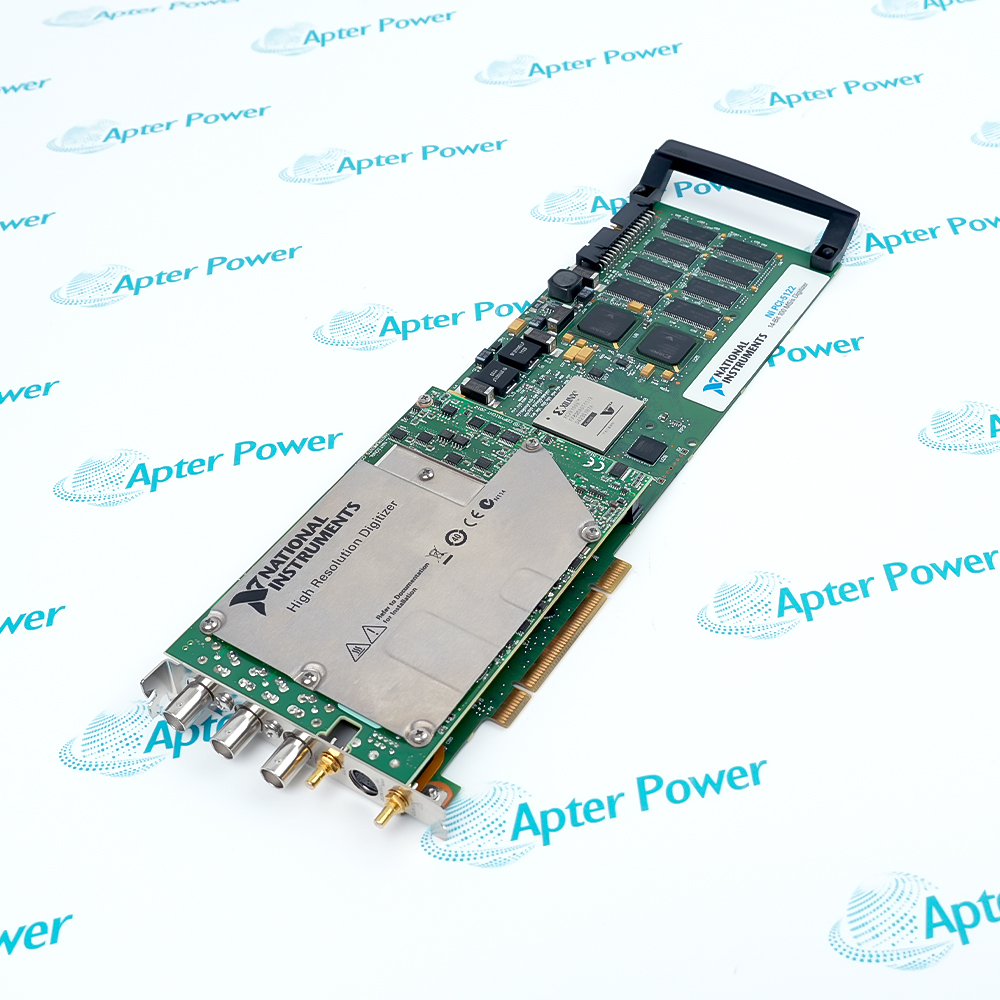
Compare the full NI PCI-6224 marking, hardware execution and mating interfaces with the installed position before approving a replacement.
-
Check the offered item before ordering
Request clear photographs of the offered PCI-6224 marking and connections. Ask the maintenance team to compare them with the applicable NI instructions and the installed circuit or system design.
Technical specifications for PCI-6224
-
Manufacturer:NI
-
Product Category:General Automation
-
Spare Part Number:PCI-6224
-
Weight:0.05 kg
-
Tariff Code:8537101190
-
Analog inputs:32 single-ended or 16 differential
-
ADC resolution:16 bits
-
Maximum aggregate sampling:250 kS/s
-
Input ranges:±0.2 V; ±1 V; ±5 V; ±10 V
-
Maximum working voltage:±11 V relative to AI GND, signal plus common mode
-
Digital lines:48
-
Input FIFO:4095 samples
-
Timing accuracy:50 ppm of sample rate
-
Digital waveform port:Port 0, up to 32 lines
Information
- Channel configuration and sampling distribution determine how the available conversion throughput is shared across the acquisition task.
Signal integrity: manage settling and common-mode voltage
Timing resources: coordinate analog, digital and counter-driven tasks
Digital waveform operations use Port 0 and require a sample clock from another supported subsystem or an external source. Static digital lines and timing terminals have separate roles. The application must assign those resources and data transfers deliberately to avoid conflicts between simultaneous measurement tasks.
Combine analog measurements with digital status under a deliberately allocated timing configuration. Use compatible trigger and PFI routing to align the acquisition task with the event of interest. Review each terminal’s selected function so a timing route does not conflict with a static digital assignment. The shared terminal cannot be treated as two independent pins.
PCI-6224 Original Technical Excerpt
Original NI technical pages applicable to PCI-6224 and its stated system context. PDF · 5 pages.PCI-6224 Installation & Verification Guide
Apter Power service guide covering preserve acquisition tasks; check analog references; assign shared digital terminals and controlled acceptance. PDF · 5 pages.
Application scope: Applications must satisfy the module or transducer boundary and the actual controller, receiver or target conditions.
Multiplexed laboratory acquisition
Distribute aggregate throughput among analog channels with suitable source impedance and settling time.PC-based machine test
Combine analog measurements with digital status under a deliberately allocated timing configuration.Triggered measurements
Use compatible trigger and PFI routing to align the acquisition task with the event of interest.Synchronized digital tasks
Supply a supported digital sample clock and check resource sharing with other device functions.
Save channel modes, scan order, ranges, clocks and trigger routes. Record the PCI installation and connector assignments used by the application.
Verify differential or single-ended returns and the common-mode boundary. Inspect the signal source impedance before selecting the fastest conversion interval.
Resolve Port 0 waveform use and PFI timing routes. Ensure static digital assignments do not conflict with trigger or clock functions.

Acquire known signals with representative inter-channel steps. Check both measurement error and sustained host transfer without overrun.
Compare timing, trigger response and analog values against the test reference. Save the accepted configuration and calibration context with the application.
Keep the affected process in its approved maintenance state until field indications and the intended control or monitoring response have both been checked.
Alternative Names
Technical notes
Configuration scope: Technical values apply to PCI-6224 with the stated operating conditions. Check supplied revision and the configured installation.
Engineering acceptance: The intended multifunction pci data acquisition device function must be accepted with its actual mating interfaces and configured system. Resolve Port 0 waveform use and PFI timing routes. Ensure static digital assignments do not conflict with trigger or clock functions.

FAQ View All FAQ
-
How does scanning more channels affect the per-channel rate of PCI-6224?The maximum multichannel rate is aggregate. Divide the available scan throughput among the configured channels and allow the required conversion interval for settling.
-
Why can a high-impedance source reduce PCI-6224 multiplexed measurement accuracy?After switching channels, the input must settle through the source impedance. Increase settling time or use an appropriate buffered source when large steps and high impedance cause errors.
-
Does differential mode protect PCI-6224 from excessive common-mode voltage?No. Signal plus common-mode voltage must remain within the working limit relative to AI GND. Differential wiring does not provide galvanic isolation.
-
Why is a full-scale step more demanding for PCI-6224 than repeated samples of one stable signal?Multiplexer switching introduces a new voltage that must settle. The required conversion interval depends on the acceptable residual error and the source conditions.
-
Can PCI-6224 digital waveform generation run from its own independent timing engine?The digital subsystem requires a supported clock from another device subsystem or an external source. Allocate that clock explicitly when designing a timed digital task.
-
How should PCI-6224 PFI lines be assigned when digital I/O and triggers coexist?Review each terminal’s selected function so a timing route does not conflict with a static digital assignment. The shared terminal cannot be treated as two independent pins.
-
Why is ADC resolution insufficient to state PCI-6224 measurement accuracy?Accuracy also includes gain, offset, temperature, nonlinearity and noise contributions. Select the input range and calibration conditions appropriate to the measurement.
-
What distinguishes an PCI-6224 FIFO problem from a signal-wiring problem?A transfer overrun concerns host and buffer servicing, whereas a wrong or noisy value may arise in the analog circuit. Check acquisition status and data-transfer timing before altering field wiring.
Supporting new and legacy automation
-
Please try to be as accurate as possible with your search.
-
We can quote you on 1000s of specialist parts, even if they are not listed on our website.
-
We can't find any results for “”.
Related cases and sourcing guidance
View all case studiesYou May Also Like
Product Browsing History
-
Whatsapp: +86 18030235313
Send us a message. -
sales13@apterpower.com
Complete our online form. -
+86 18030235313
Speak to our team in your native language.