Speak to a sourcing specialist
sales13@apterpower.com

T8243

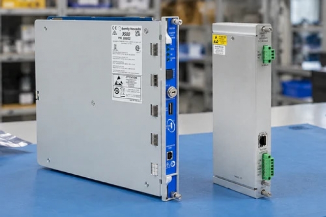
Power Supply Diagnostic Interface
Product image is representative; revision or series may vary. Contact us to request a specific version.

Product Describe:

ICS Triplex T8243 converts Trusted Power Pack and shelf status signals into volt-free alarm contacts. It plugs into the rear of the Power Shelf and provides connections for system monitoring and the optional Power Controller.
  • Manufacturer part number
    T8243
  • Shipping
    Swift global dispatch
  • Condition
    New, original product
  • Shipping size (est.)
    8.5cm x 5.4cm x 7.6cm
  • Country of Origin
    USA
Get a quick price for T8243
E-mail *
Mobile *
Company
Content *
Quantity *
Upload (gif, jpg, jpeg, png, bmp, doc, docx, xls, xlsx, ppt, pdf, csv)
For more information on how your data is processed and stored by Apterpower please read our privacy policy

What happens after you enquire

  • 0

    Review your reference

    Send the T8243 reference, installed shelf arrangement and clear connection photographs.

  • 1

    Confirm the offer

    Compare the offered T8243, connectors and itemized accessories with the required power-system position.

  • 2

    Arrange dispatch

    Confirm quantity, delivery details and the agreed dispatch date before shipment arrangement.

  • Match the complete marking

    Provide the full T8243 marking and photographs showing the installed shelf and connections.

  • Check the offered item before ordering

    Request photographs of the offered T8243. Have your maintenance team compare its connections and supplied accessories with the installed assembly and applicable original instructions.

Technical specifications for T8243

  • Manufacturer:
    ICS Triplex
  • Product Category:
    PLC Systems
  • Spare Part Number:
    T8243
  • Weight:
    0.5 kg
  • Tariff Code:
    8537101190
  • External interface supply:
    24 V DC
  • Source fuse:
    500 mA, F-rated, near the source
  • Internal electronics supply:
    Regulated 5 V
  • Shelf connection CON1:
    25-way male D-sub
  • Extended connection CON2:
    25-way female D-sub
  • Alarm/supply connector CON3:
    10 ways
  • CON3 supply terminals:
    Pin 1: +24 V; pin 6: 0 V
  • CON3 DC alarm pairs:
    2–3: pack 1; 3–4: pack 2; 4–5: pack 3
  • CON3 AC alarm pairs:
    9–10: pack 1; 8–9: pack 2; 7–8: pack 3
  • DC alarm combination:
    DCFAIL OR over-temperature protection
  • Healthy alarm contact:
    Closed, relay energized
  • Alarm contact state:
    Open, relay de-energized
  • Shelf-address jumpers:
    J1 and J2
  • Address combinations:
    4 shelf addresses / up to 12 pack addresses
  • CON2 serial-data terminals:
    Pin 5: SDA; pin 6: SCL
  • CON2 controller supply:
    Pin 7: 24 V from Power Port
  • CON2 current-sharing terminal:
    Pin 24: CS
  • CON2 internally linked pins:
    19, 20 and 25
  • CON3 cable block:
    Weidmuller BLZF3.5/10
  • Fault-relay contact form:
    SPDT
  • Fault-relay resistive load:
    0.5 A at 125 V AC; 1 A at 24 V DC
  • Fault-relay maximum switching power:
    62.5 VA or 30 W

Information

Overview Downloads Applications / Compatibility Product Precautions
  • ICS Triplex T8243 gives the control system separate AC and DC fault paths for each pack position. Its relay logic also means a missing interface supply must be distinguished from a genuine failure of all connected packs.
Fault aggregation: Each DC contact combines the corresponding DC-output-fail and over-temperature signals.
Healthy-state signalling: Alarm contacts close with energized healthy relays and open in the alarm state.
Shared system interface: A second D-sub connection extends the control and current-sharing path to compatible equipment.
CON1 mates with the Power Shelf, while CON2 extends the interface to other compatible shelves or a controller. CON3 carries the system supply and six pack-related alarm contact pairs. The Power Port is retained by D-sub jack screws; it is an interface accessory, not an AC-to-DC Power Pack.

The external 24 V supply powers the relays and is regulated internally for the low-voltage electronics. The supply requires a 500 mA F-rated fuse near its source; an additional non-replaceable fuse is present on the interface. Loss of this auxiliary supply can open healthy-state contacts even while a separately powered DC bus remains energized.

J1 and J2 select one of four shelf addresses for the I2C control bus. These jumpers identify the shelf rather than changing the alarm logic. The interconnect must follow a common DC bus, and independent supplies must not be joined through it merely to obtain a convenient monitoring connection.
Controller platform reference: Trusted distributed power system. Retain busbar separation, pack allocation and diagnostic wiring.
The two documents for T8243 separate original Trusted hardware information from a field verification workflow. View PDF supplies a distinct engineering explanation of the component and its system boundaries.
Original manufacturer pages retain their technical context. Use the Apter Power guide with the applicable manufacturer instructions and approved installation design.
System and supply context: T8243 is a plug-in diagnostic interface for the Trusted Power Shelf. It requires its own 24 V system connection and does not replace the shelf, Power Packs or optional controller.

Application scope: Integrate the volt-free alarm contacts with an engineered monitoring circuit. Pack state, interface power and field wiring must all be considered when the controller interprets an open contact.
Prepare ICS Triplex T8243 for its configured installation using these checks.
Protect the auxiliary supply

Use the specified source fuse and preserve correct polarity on CON3 pins 1 and 6.

Trace shared alarm terminals

Identify each contact pair and any intentional series links before disturbing the ten-way connector.

Respect contact loading

Check monitoring-circuit voltage, current and load type against the relay limits.

Keep shelf addresses unique

Record J1/J2 positions and prevent duplicate shelf addresses within one controller group.

Do not join separate buses

Keep the current-sharing interconnect out of independent A/B supply paths.

Validate alarm causes separately

Test interface-power loss and pack-fault response as different conditions under the approved maintenance procedure.

Alternative Names

Trusted T8243 power supply diagnostic interface ICS Triplex T 8243

Technical notes

Combined DC indication: An open DC contact can represent either DCFAIL or over-temperature protection. The contact alone does not identify which input caused the alarm.

Supply-loss interpretation: All relays depend on the Power Port supply. Several open contacts with a live DC bus can indicate interface-supply or common wiring loss rather than simultaneous pack failures.

Empty pack positions: Link only the specified contacts for intentionally unoccupied positions. Bridging a contact from an installed faulty pack suppresses a required diagnostic path.

Fan-fault limitation: The fault table distinguishes a locked fan rotor from an actual over-temperature trip. An amber indication does not necessarily mean the DC alarm contact has opened.


FAQ View All FAQ

  • Why might all T8243 alarm inputs change even though the DC bus remains live?
    Check the Power Port 24 V supply, its source fuse and common monitoring wiring. Its relays depend on that auxiliary supply, so its loss can open contacts without proving that all separate Power Packs stopped producing output.
  • Can one open DC contact on T8243 distinguish over-temperature from output failure?
    No. DCFAIL and the over-temperature protection signal are combined for that pack. Compare local indications and the relevant electrical and thermal conditions to identify the cause.
  • Does an amber fan indication always open the T8243 DC alarm contact?
    No. The fault table shows a locked fan rotor with amber indication while AC and DC contacts remain closed and output remains on. An over-temperature trip opens the DC contact. Do not treat these conditions as identical.
  • What happens if two T8243 interfaces retain the default shelf address?
    The controller bus can encounter duplicate pack addresses. Set a unique J1/J2 combination for each shelf in the controller group before applying the required startup sequence.
  • Why must the input wiring plan identify adjacent T8243 CON3 contact terminals?
    The DC pairs are 2–3, 3–4 and 4–5; the AC pairs are 7–8, 8–9 and 9–10. Adjacent pairs share terminals, so the physical connector must not be treated as six completely separate two-terminal groups.
  • Can a T8243 controller cable connect shelves on separate A/B busbars?
    No. The interconnect also carries current-sharing signals. Connecting separate buses can make the supplies attempt to share between unconnected outputs and can damage sensing circuits.
  • Should a missing-pack alarm on T8243 be cleared by bridging every open contact?
    No. Apply the specified links only to positions intentionally left without a pack. Diagnose an installed pack alarm and preserve its monitoring function rather than masking it.
  • How should T8243 be tested after restoring its 24 V supply?
    Establish a healthy baseline, then verify each assigned AC and DC alarm path against the intended pack position. Check the controller interpretation, supply-loss response and recovery without assuming that restored relay power alone proves all field wiring correct.
SPEAK TO OUR TEAM
Let’s find the right solution for you.
Send us the part number, quantity and delivery destination. Our team will help confirm availability and lead time.
  • Whatsapp: +86 18030235313

    Send us a message.
  • sales13@apterpower.com

    Complete our online form.
  • +86 18030235313

    Speak to our team in your native language.