-
Match the complete marking
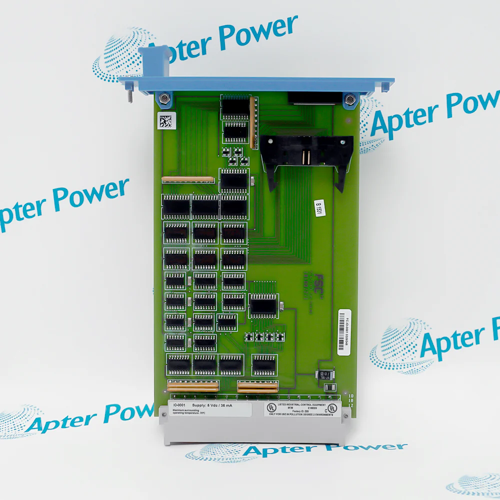
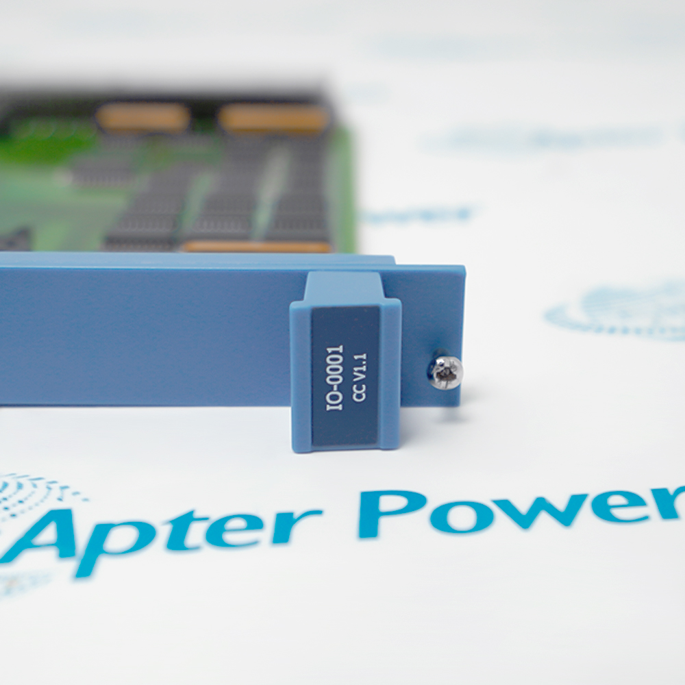
Include FC-IO-0001 V1.1 and any revision or assembly number visible on the item. Keep the exact reference on your enquiry and quotation.
-
Check the offered item before ordering
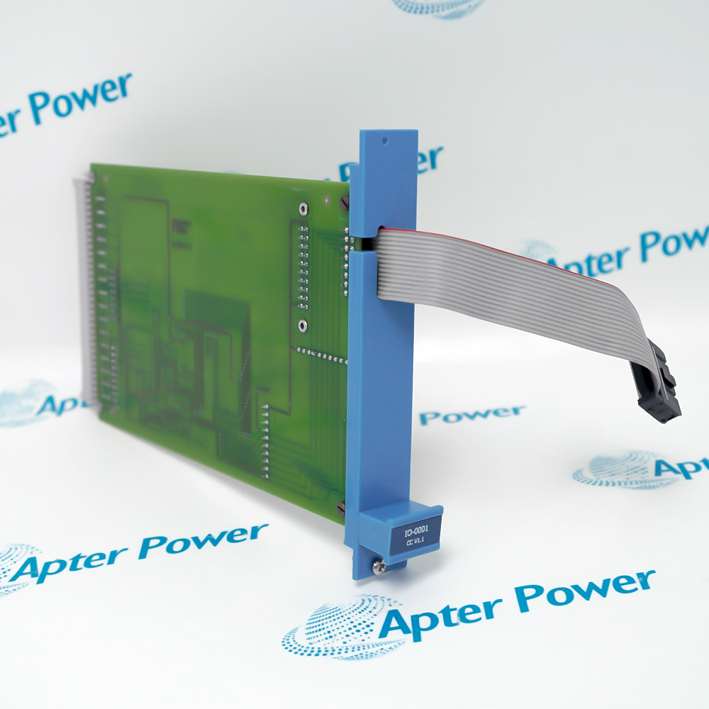
Request available label and connector photos. Have your maintenance team compare the offered FC-IO-0001 V1.1 with the installed equipment and applicable Honeywell documentation.
Technical specifications for FC-IO-0001 V1.1
-
Manufacturer:Honeywell
-
Product Category:DCS Systems
-
Spare Part Number:FC-IO-0001 V1.1
-
Weight:0.1 kg
-
Tariff Code:8537101190
-
Function:Control Processor to I/O communication
-
Non-redundant chassis:IOCHAS-0001S: 1 module in slot 21
-
Redundant chassis:IOCHAS-0001R: modules in slots 20 and 21
-
Control Processor connection:CN1
-
Address selection connection:CN3
-
Bus connection:Front flat-cable connection
-
Connector:DIN 41612 type F male; d/b/z rows
-
Chassis addressing:CA0–CA3; addresses 1–9
-
Supply:5 Vdc
-
Current:35 mA
-
Supply ripple:Less than 50 mV peak-to-peak
-
Coating:FC conformal-coated type
Information
- FC-IO-0001 V1.1 maintains the processor-to-I/O bus relationship and chassis-address connection in the configured Safety Manager installation.
Connection: Horizontal I/O bus and chassis address selection
Design: FC conformal-coated interface
The interface connects to the Control Processor through CN1 and to the horizontal I/O bus through the front flat-cable connection. CN3 provides the chassis-address selection connection. The module uses a DIN 41612 type F male connector with d, b and z rows; the complete connector and cable arrangement must match the installed chassis.
Chassis address selection uses CA0 through CA3 and supports addresses 1 through 9 in the documented arrangement. The design supply is 5 Vdc at 35 mA, with ripple below 50 mV peak-to-peak. Powered replacement can cause a shutdown when safety-related I/O is involved, so isolate or manage the process under the approved Safety Manager procedure before removing the interface.
-
Honeywell FC-IO-0001 V1.1 technical reference
Original Honeywell excerpt - PDF, 8 pages, 145.2 KB. The listed interface and supply values describe IO-0001. Match the offered FC-IO-0001 V1.1 to the installed chassis and revision; the reference data-sheet version is not a separate unit-approval statement. -
Honeywell FC-IO-0001 V1.1 installation planning guide
Prepared by Apter Power - PDF, 5 pages, 96 KB. Identity, configuration, connection and controlled acceptance planning.
Platform applications: The following applications describe Safety Manager functions. Match the complete FC-IO-0001 V1.1 identity to the installed system before selecting a replacement.
-
Non-redundant I/O
Link one Control Processor communication path to the applicable non-redundant I/O chassis. -
Redundant I/O
Maintain the paired communication paths in the documented redundant chassis arrangement. -
Chassis identification
Preserve the address-selection connection and installed CA0–CA3 configuration. -
I/O service recovery
Restore processor-to-I/O communication and verify channel behavior after controlled maintenance.
Match FC-IO-0001 V1.1, the chassis type and the installed I/O configuration.
Assess safety-related I/O before powered removal; replacement can initiate a shutdown.
Use slot 21 for the documented non-redundant arrangement and slots 20/21 for redundancy.
Record and preserve CN1, CN3 and horizontal-bus flat-cable orientation.
Verify the existing CA0–CA3 selection and avoid duplicate or incorrect chassis addresses.
Confirm the processor communication path and controlled field response before normal service.
Alternative Names
Technical notes
Installation relationship: The interface connects to the Control Processor through CN1 and to the horizontal I/O bus through the front flat-cable connection. CN3 provides the chassis-address selection connection. The module uses a DIN 41612 type F male connector with d, b and z rows; the complete connector and cable arrangement must match the installed chassis.
Configuration: The listed interface and supply values describe IO-0001. Match the offered FC-IO-0001 V1.1 to the installed chassis and revision; the reference data-sheet version is not a separate unit-approval statement.
Technical reference: Honeywell Safety Manager Hardware Reference, EP-SM.MAN.6284, Release 162 Issue 1.10.

FAQ View All FAQ
-
What is the role of FC-IO-0001 V1.1?The IO-0001 interface transfers communication between the Control Processor and the I/O modules.
-
Where does FC-IO-0001 V1.1 fit in a non-redundant chassis?The IOCHAS-0001S arrangement uses one IO-0001 module in slot 21.
-
How is FC-IO-0001 V1.1 arranged in a redundant chassis?The IOCHAS-0001R arrangement uses two IO-0001 interfaces in slots 20 and 21.
-
Which connections are used by FC-IO-0001 V1.1?CN1 connects to the Control Processor, the front flat cable connects to the horizontal I/O bus, and CN3 connects to chassis-address selection.
-
What connector design applies to FC-IO-0001 V1.1?The IO-0001 design uses a DIN 41612 type F male connector with d, b and z rows.
-
How is chassis addressing associated with FC-IO-0001 V1.1 selected?The documented arrangement uses CA0 through CA3 for chassis addresses 1 through 9. Preserve the installed address selection.
-
What supply requirements apply to the design of FC-IO-0001 V1.1?The design uses 5 Vdc at 35 mA, with supply ripple below 50 mV peak-to-peak. Confirm applicability to the actual marked unit.
-
Can FC-IO-0001 V1.1 be replaced without affecting safety-related I/O?Do not assume that. Powered replacement can cause a shutdown where safety-related I/O is involved; follow the approved system procedure.
Supporting new and legacy automation
-
Please try to be as accurate as possible with your search.
-
We can quote you on 1000s of specialist parts, even if they are not listed on our website.
-
We can't find any results for “”.
You May Also Like
Product Browsing History
-
Whatsapp: +86 18030235313
Send us a message. -
sales13@apterpower.com
Complete our online form. -
+86 18030235313
Speak to our team in your native language.