-
Match the complete marking
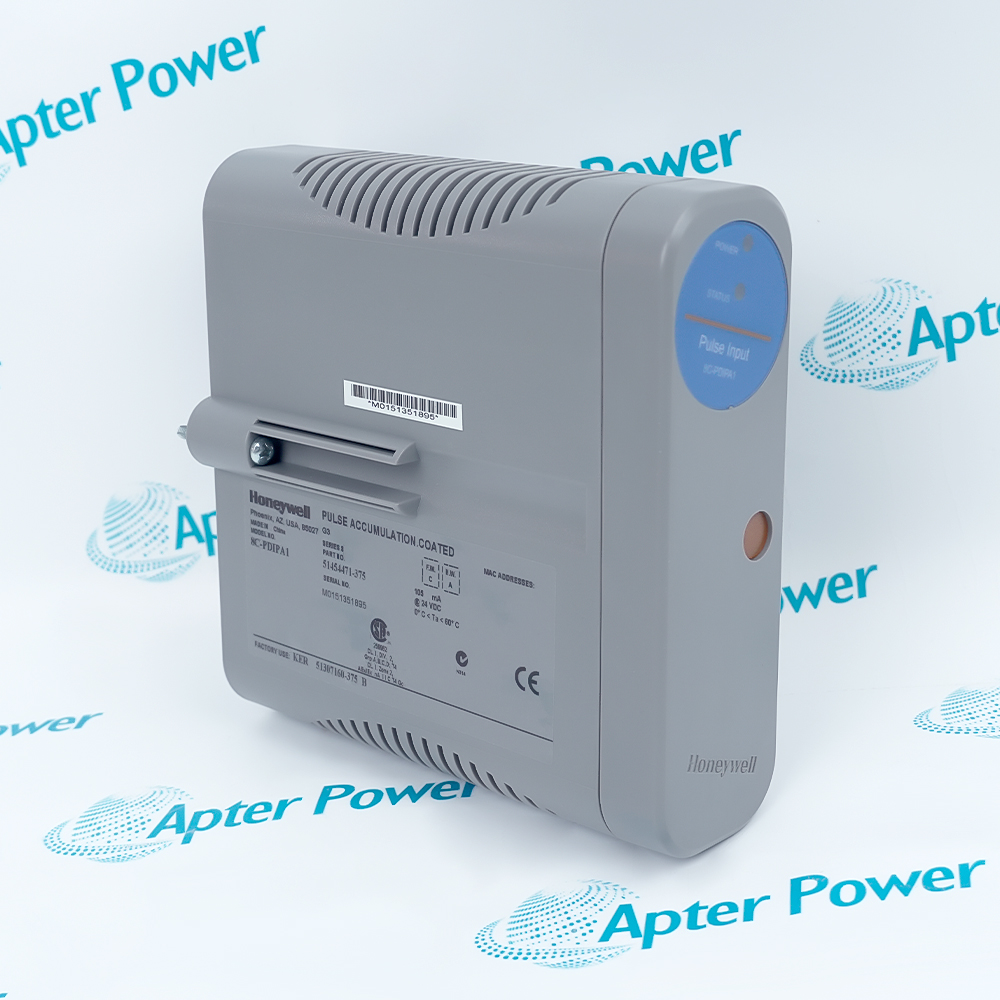
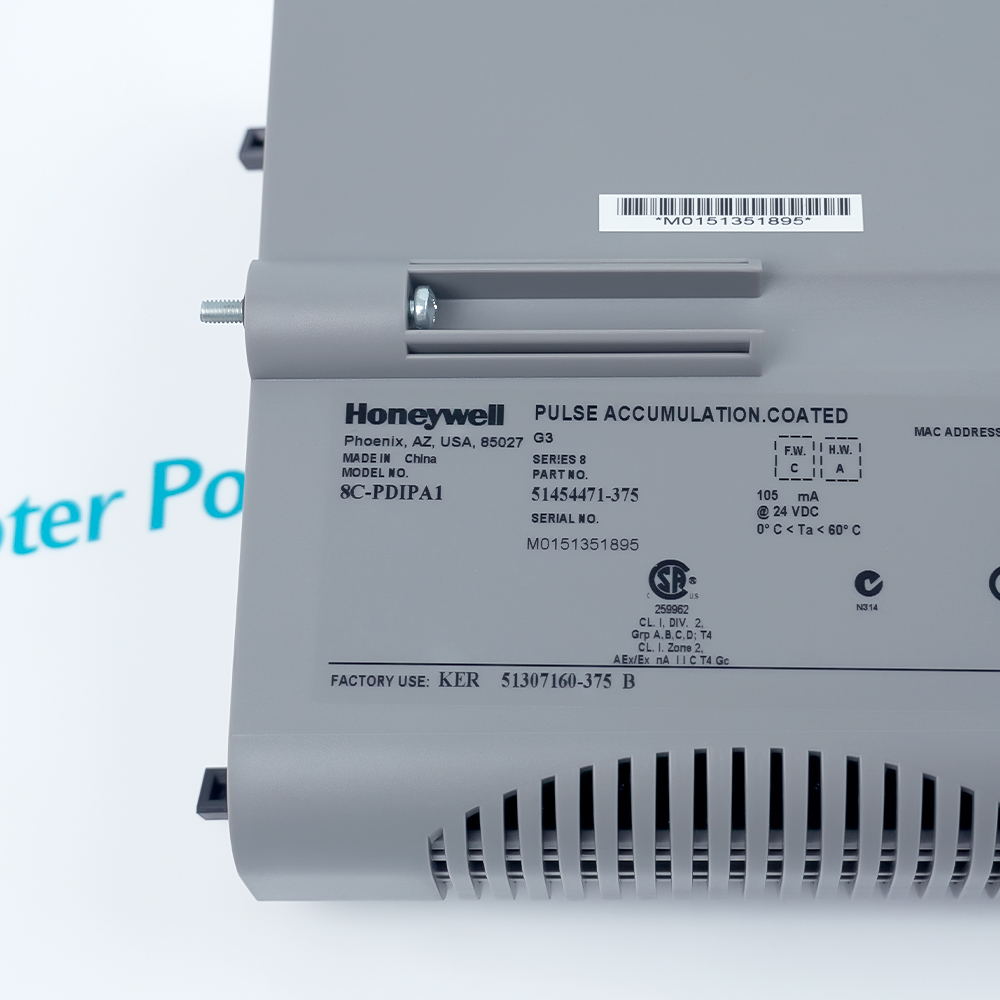
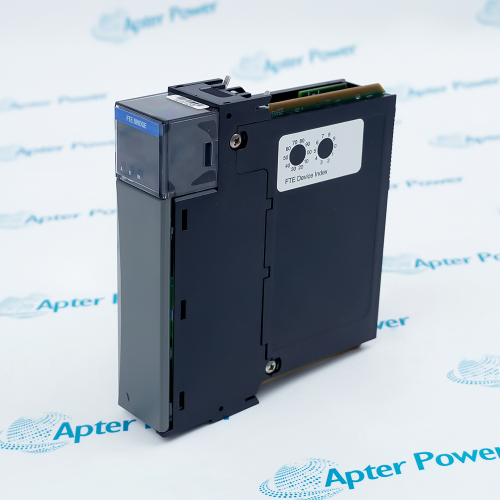
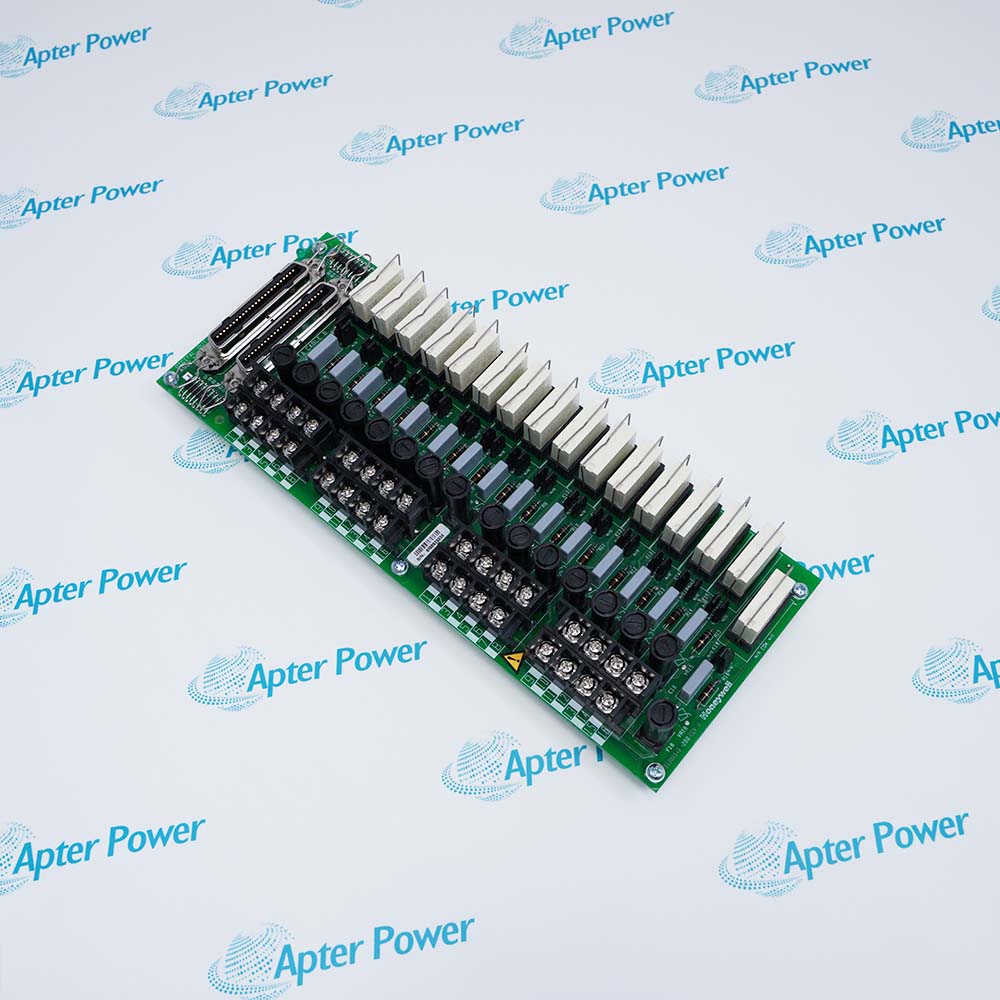
Send the full module marking and IOTA label photo. The coated module and fitted IOTA must match the intended C300 position.
-
Check the offered item before ordering
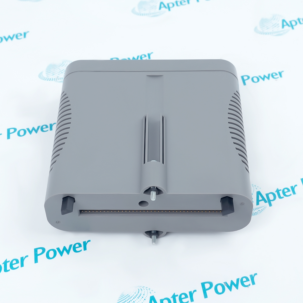
Request a photo of the offered module label and connector. Your maintenance team should compare them with the installed 8C-PDIPA1 and the applicable Honeywell Series 8 specification before ordering.
Technical specifications for 8C-PDIPA1 51454471-375
-
Manufacturer:Honeywell
-
Product Category:DCS Systems
-
Spare Part Number:8C-PDIPA1 51454471-375
-
Weight:0.3 kg
-
Tariff Code:8537101190
-
Input channels:32
-
Pulse-capable channels:1-16, individually configured
-
Discrete-only channels:17-32
-
Voltage rating:24 VDC
-
External DI power range:18-30 VDC
-
Module current rating:105 mA
-
Pulse frequency:0-1 kHz at minimum 30% duty cycle
-
Minimum pulse width:300 µs
-
Per-channel scan time:300 µs
-
ON threshold:13 VDC minimum or 3 mA minimum
-
OFF threshold:5 VDC maximum or 1.2 mA maximum
-
Input impedance:4.2 kΩ
-
Input-filter/isolation delay:5 ms ±20%
-
Galvanic isolation:1000 VAC RMS, external-field-power arrangement
-
Nonredundant IOTA:8C-TDILA1, coated
-
Redundant IOTA:8C-TDILB1, coated
Information
- A Series 8 IOTA connects the field circuits to the module; the C300 application assigns each configured input its process meaning.
Power boundary: Choose the documented internal or user-supplied field-power arrangement
Redundancy path: Use the matching redundant IOTA when the host configuration requires it
Acceptance focus: Compare channel mode, pulse behavior and diagnostics against the saved project
For user-supplied field power, Honeywell specifies an 18-30 VDC DI power range and a 24 VDC module voltage rating. The module current rating is 105 mA. Optical isolation is implemented in the I/O module; the listed 1000 VAC RMS galvanic-isolation figure is subject to the external-power arrangement defined in the specification.
A pulse input accepts a 0-1 kHz source when the device meets the minimum 30% duty-cycle condition. The minimum pulse width and individual-channel scan time are each 300 microseconds. Confirm the real sensor waveform and input-filter delay before relying on the counted value for alarms or maintenance trends.
-
Apter Power technical reference for Honeywell 8C-PDIPA1 51454471-375
Honeywell technical-reference excerpt - PDF, 1 page. Documented product identity, system role and applicable technical details. -
Honeywell 8C-PDIPA1 51454471-375 installation guide
Prepared by Apter Power - PDF, 3 pages. Identification, installation checks, commissioning and fault isolation.
Application scope: Use discrete inputs for process state and the first 16 channels for configured pulse counting or frequency measurement where the sensor waveform meets the stated limits.
-
Discrete process states
Map contact or powered-state inputs into the C300 project with the correct threshold and field-power selection. -
Pulse totalization
Assign a pulse-capable channel to count a qualified sensor waveform and preserve the engineering-unit conversion in the control strategy. -
Frequency monitoring
Use the configured pulse function for frequency measurement when the source duty cycle and pulse width are within the specified limits. -
Redundant I/O arrangement
Pair with 8C-TDILB1 where the installed Series 8 design uses the documented redundant IOTA path.
Record the 32 point assignments and which of channels 1-16 use pulse mode before removing hardware.
Identify internal versus external power at the IOTA; apply the specified external supply range only to a user-supplied arrangement.
Measure the source frequency, duty cycle and pulse width at the input under operating conditions.
Do not interpret the 1000 VAC RMS isolation value as permission to omit circuit separation or grounding design.
Verify 8C-TDILA1 or 8C-TDILB1 and the redundant configuration before fitting the module.
Challenge a discrete point and a pulse point, compare counts, frequency, diagnostics and controller values with the saved baseline.
Alternative Names
Technical notes
Installation relationship: The C300, Series 8 IOTA and field-power selection define the input circuit and its point mapping.
Pulse qualification: The source waveform must satisfy the specified frequency, width and duty-cycle conditions before totalization is accepted.
Technical reference: Honeywell Series 8 Controller and I/O Specification, S803-150-520, Version 1.0. Product and purchasing information are separate.

FAQ View All FAQ
-
Why can 8C-PDIPA1 51454471-375 show a correct contact state but an incorrect pulse total?A discrete threshold can be satisfied while a pulse source violates the 300 µs minimum width or the minimum 30% duty cycle. Measure the waveform at the IOTA and review the configured totalization scale.
-
How should the first sixteen channels of 8C-PDIPA1 51454471-375 be commissioned?Record the intended DI or pulse mode separately for each channel, verify the connected device and field-power selection, then challenge both the raw channel state and the C300 application value.
-
What happens if a pulse signal on 8C-PDIPA1 51454471-375 exceeds its documented frequency range?Counts may no longer represent the source reliably. Check the source against the 0-1 kHz condition and the specified duty cycle, and use a suitable input design if the waveform falls outside those limits.
-
When does the isolation rating of 8C-PDIPA1 51454471-375 apply?The 1000 VAC RMS system-to-field figure is specified for the external user-supplied power option. Confirm the IOTA power arrangement and full cabinet separation before applying that rating to an installation.
-
How can an apparently stuck input on 8C-PDIPA1 51454471-375 be isolated?Compare the field voltage or current with the ON and OFF thresholds at the IOTA, inspect the wiring and power return, and then compare raw channel status with the C300 project point.
-
Can 8C-PDIPA1 51454471-375 be moved from a nonredundant to a redundant position without a configuration review?No. Verify the 8C-TDILB1 redundant IOTA, paired slot, controller project and state-transfer logic before changing the installed arrangement.
-
Why might a rapid change be missed by 8C-PDIPA1 51454471-375 even though the wiring is sound?Check pulse width and the specified 5 ms ±20% input-filter/isolation delay against the event timing. A short transient below the qualified input condition may not be represented as the application expects.
-
What is a useful acceptance test after replacing 8C-PDIPA1 51454471-375?Exercise representative OFF and ON states, inject a qualified pulse train on a configured channel, compare total and measured frequency, and review module diagnostics and the controller event record.
Supporting new and legacy automation
-
Please try to be as accurate as possible with your search.
-
We can quote you on 1000s of specialist parts, even if they are not listed on our website.
-
We can't find any results for “”.
Related cases and sourcing guidance
View all case studiesYou May Also Like
Product Browsing History
-
Whatsapp: +86 18030235313
Send us a message. -
sales13@apterpower.com
Complete our online form. -
+86 18030235313
Speak to our team in your native language.