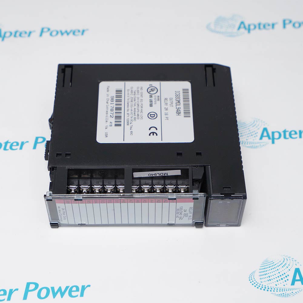
-
Match the complete marking
Include IC697VAL314 and any revision or assembly number visible on the item. Keep the exact reference on your enquiry and quotation.
-
Check the offered item before ordering
Request available label and connector photos. Have your maintenance team compare the offered IC697VAL314 with the installed equipment and applicable GE documentation.
Technical specifications for IC697VAL314
-
Manufacturer:General Electric
-
Product Category:PLC Systems
-
Spare Part Number:IC697VAL314
-
Weight:0.4 kg
-
Tariff Code:8537101190
-
Output channels:4 isolated channels
-
Output signal:4–20 mA current
-
Resolution:12 bit
-
Channel numbering:0–3
-
Loop supply:Internal 15 V or external supply up to 30 V
-
Loop-supply selection:Per-channel jumpers
Information
- IC697VAL314 serves the isolated four-channel analog output module role in a configured General Electric system; selection starts with the installed host and full marking.
Fault isolation: Separate command, supply, load and cable
Acceptance: Exercise each output against approved test points
The module provides four 4–20 mA channels, numbered 0 through 3, with 12-bit resolution. The GE user manual describes internal 15 V loop power or an external loop supply up to 30 V, selected with channel jumpers. The eight-channel IC697VAL318 is a separate model and its channel count must not be assigned to IC697VAL314.
Application design must retain the programmed output scaling, loop-power choice, field wiring and safe process state. During replacement, record jumper positions and channel assignments, then compare command, measured loop current and field-device response for every affected output.
-
General Electric IC697VAL314 technical reference
Apter Power technical reference - PDF, 2 pages. Product identity, engineering context and applicability conditions. -
General Electric IC697VAL314 installation guide
Prepared by Apter Power - PDF, 1 page. Configuration review, safe installation and functional acceptance.
Compatibility scope: Match the four-channel assignment, field terminal arrangement and per-channel loop-power jumper setting; the eight-channel IC697VAL318 is a different module.
-
Process analog control
Drive compatible 4–20 mA final-control or indication loops from a configured GE rack. -
Four-channel restoration
Replace a matched IC697VAL314 while preserving output assignments 0 through 3. -
Internally powered loops
Use the documented 15 V internal loop option where the approved circuit permits it. -
Externally powered loops
Use a suitable external supply within the documented limit and matched jumper setting.
Coordinate process isolation and output handover before removal.
Photograph each channel loop-supply selection before exchange.
Preserve terminal and field-device connections.
Do not mix internal and external loop supplies inadvertently.
Retain engineering-unit and failsafe configuration.
Compare commanded current and field response for channels 0–3.
Alternative Names
Technical notes
Technical basis: GE Fanuc GFK-2093, PACSystems RX7i module listing, and GFK-2057, Analog Output Modules IC697VAL314/318 User Manual.
Applicability: GFK-2093 and GFK-2057 identify IC697VAL314 directly. The four-channel, 12-bit and loop-supply entries apply to this exact module, not the eight-channel IC697VAL318.

FAQ View All FAQ
-
How should loop power be selected on IC697VAL314?Use the channel jumpers to match the installed internal 15 V or approved external supply arrangement.
-
What happens if an external supply is connected to IC697VAL314 with the wrong jumper setting?The loop may not operate correctly and could be damaged; compare the jumper and circuit diagram before energization.
-
How can an open loop on IC697VAL314 be diagnosed?Check current at the terminal, cable continuity, supply, load and channel diagnostics.
-
Why should IC697VAL318 data not be applied to IC697VAL314?IC697VAL318 has eight outputs while IC697VAL314 has four; use the exact module number and channel map.
-
What should be saved before removing IC697VAL314?Record output scaling, channel assignments, supply jumpers, load wiring and any failsafe values.
-
Can the current outputs of IC697VAL314 be used as voltage outputs by rewiring?No. The documented IC697VAL314 execution is a 4–20 mA current-output module.
-
How should an output reading offset be investigated on IC697VAL314?Compare command value, loop current, supply headroom, load resistance and calibration configuration.
-
What acceptance test follows replacement of IC697VAL314?Exercise all four channels over approved test points and verify controlled field-device response and alarms.
Supporting new and legacy automation
-
Please try to be as accurate as possible with your search.
-
We can quote you on 1000s of specialist parts, even if they are not listed on our website.
-
We can't find any results for “”.
Related cases and sourcing guidance
View all case studiesYou May Also Like
Product Browsing History
-
Whatsapp: +86 18030235313
Send us a message. -
sales13@apterpower.com
Complete our online form. -
+86 18030235313
Speak to our team in your native language.