-
Match the complete marking
Match the complete Emerson PR9350-02-S2 marking and the installed configuration. Confirm the fixed-cable S2 version and its conductor assignments.
-
Check the offered item before ordering
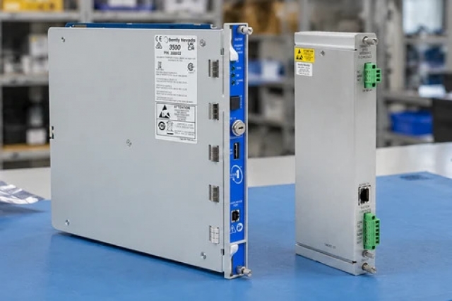
Please request clear photographs of Emerson PR9350-02-S2, including its complete label and interfaces. Ask your maintenance team to compare the offered unit with the installed equipment and the applicable Emerson PR9350 installation instructions before approving the order.
Technical specifications for PR9350-02-S2
-
Manufacturer:Emerson
-
Product Category:Machinery Monitoring Systems
-
Spare Part Number:PR9350-02-S2
-
Weight:1.66 kg
-
Tariff Code:8537101190
-
Measuring interval:±25 mm
-
Fixed cable:10 m; open ends
-
Construction:Oil-proof version
-
Excitation voltage:5 Vrms
-
Excitation current:27–50 mA
-
Carrier frequency:3–5 kHz
-
Bridge sensitivity:270 mV/V
-
Full-range linearity:±3.5%
-
Linearity over 60% range:±0.5%
-
Coil A / B / C:Brown / white / green
-
Shield conductor:Black; not bonded to sensor housing
-
Operating temperature:-20 to +100 °C
Information
- Emerson PR9350-02-S2 carries a displacement signal from a moving ferromagnetic core to remote measuring electronics through its fixed cable. The two winding impedances change in opposite directions around the mechanical centre position.
Selected connection: Fixed 10 m cable, open ends, oil-proof version
Excitation: 5 Vrms at 3–5 kHz
The S2 version uses a fixed 10 m cable instead of the standard sensor socket arrangement. Brown, white and green conductors correspond to coil connections A, B and C. The black conductor is the cable shield and is not connected to the sensor housing. The tracing pin uses an M3 mechanical connection and the sensor has M4 fixing points.
For the /02 measurement design, bridge sensitivity is 270 mV/V and excitation is 5 Vrms, 27–50 mA, at 3–5 kHz. Linearity error is ±3.5% over the full interval and ±0.5% over 60% of that interval. The A6500-LC converter and A6500-UM card provide the preferred measurement path; their configuration must match the installed transducer.
PR9350-02-S2 Official Technical Excerpt
Technical material for Emerson PR9350-02-S2 covers the S2 cable variant, conductor assignments and /02 measurement data. PDF · 8 pages.PR9350-02-S2 Installation & Verification Guide
Apter Power installation and verification guide covering fixed-cable termination, linkage alignment, bridge excitation and travel checks. PDF · 5 pages.
Application scope: The transducer measures linear movement. Force, pressure or other quantities require a mechanical arrangement that first converts them into an appropriate displacement.
Linear travel
The tracing pin follows the target through the ±25 mm interval while the differential coils produce the measurement signal.Remote open-end wiring
The 10 m fixed lead reaches the receiving electronics without an intermediate standard sensor plug.Carrier-bridge measurement
The two coil impedances form part of the external AC-excited bridge that generates a displacement voltage.Converted mechanical quantities
An appropriate linkage can translate another physical quantity into linear movement within the sensor travel.
Supply the sensor through the specified carrier-frequency electronics, not a direct industrial DC source.
Connect brown A, white B and green C consistently; identify the black shield separately.
Align the moving target and tracing pin so the linkage remains free over the operating travel.
Inspect the fixed lead for damage and preserve strain relief at the housing and termination.
Distinguish winding resistance from the resistance of the 10 m cable and the instrument leads.
Move through known reference positions and verify polarity, scaling and return to centre.
Alternative Names
Technical notes
Signal relationship: The sensor requires an AC carrier bridge, not a direct 24 VDC transmitter supply. The bridge output per volt of excitation is a sensitivity relationship, not a standalone current-loop output.
Installation boundary: Identify A, B and C at the fixed cable ends before testing. The published coil-resistance bands describe the sensor; allow for the additional cable resistance when testing from the remote cable end.
Technical basis: Emerson PR9350 / K20-315 Installation Guide, MHM-97864 Rev. 1.6. The /02 measuring ratings apply to the ±25 mm design; S2 specifies the fixed 10 m oil-proof cable version. K20-315 assembly properties are excluded.

FAQ View All FAQ
-
Which conductor is the centre coil connection on PR9350-02-S2?White is coil connection B. Brown is A and green is C; identify the three conductors before connecting the bridge input.
-
Is the black conductor of PR9350-02-S2 connected to its housing?No. It is the cable shield and is not connected to the sensor housing. Terminate it according to the receiving system grounding arrangement.
-
What distinguishes PR9350-02-S2 from the standard PR9350/02 connection?The S2 version is oil-proof and has a fixed 10 m cable with open ends. The standard connector arrangement must not be assumed for this version.
-
Can PR9350-02-S2 be powered directly from 24 VDC?No. The sensor requires 5 Vrms excitation at a 3–5 kHz carrier frequency, with 27–50 mA supply current. Use compatible measuring-bridge electronics.
-
Why does PR9350-02-S2 need separate checks at centre and at travel limits?The differential windings balance at the centre; their impedances diverge with movement. Check centre balance, output direction and the usable ±25 mm travel to verify both the linkage and electrical scaling.
-
How does the specified linearity of PR9350-02-S2 vary with the used interval?For the /02 design, linearity error is ±3.5% over the full range and ±0.5% over 60% of the measuring range. The smaller figure cannot be applied to full travel.
-
What should be considered when resistance-testing PR9350-02-S2 through its 10 m cable?The /02 coil bands are approximately 33.0–36.8 Ω per half winding and 66.0–73.6 Ω across both. Remote measurements also include cable and test-lead resistance; zero or an open circuit requires further investigation.
-
Can the core of PR9350-02-S2 measure pressure without a mechanical conversion?No. The sensor measures linear displacement of its tracing pin. Pressure measurement requires suitable accessories that convert pressure into displacement within the selected range.
Supporting new and legacy automation
-
Please try to be as accurate as possible with your search.
-
We can quote you on 1000s of specialist parts, even if they are not listed on our website.
-
We can't find any results for “”.
Related cases and sourcing guidance
View all case studiesYou May Also Like
Product Browsing History
-
Whatsapp: +86 18030235313
Send us a message. -
sales13@apterpower.com
Complete our online form. -
+86 18030235313
Speak to our team in your native language.