Speak to a sourcing specialist
sales13@apterpower.com

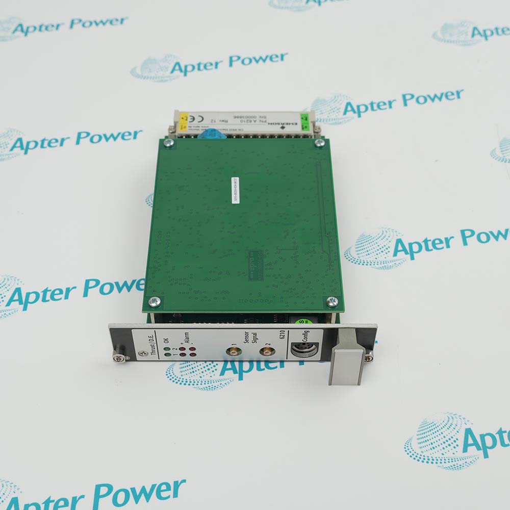
IC695ALG608

Non-Isolated Differential Analog Input Module
Product image is representative; revision or series may vary. Contact us to request a specific version.

Product Describe:

Emerson IC695ALG608 is a non-isolated differential analog input module. Software configuration assigns voltage or current measurement and selects single-ended or differential acquisition.
  • Manufacturer part number
    IC695ALG608
  • Shipping
    Swift global dispatch
  • Condition
    New, original product
  • Shipping size (est.)
    3.5cm x 13.3cm x 13.5cm
  • Country of Origin
    USA
Get a quick price for IC695ALG608
E-mail *
Mobile
Company
Content *
Quantity *
Upload (gif, jpg, jpeg, png, bmp, doc, docx, xls, xlsx, ppt, pdf, csv)
For more information on how your data is processed and stored by Apterpower please read our privacy policy

What happens after you enquire

  • 0

    Review your reference

    Send the complete IC695ALG608 reference, label photographs and required quantity. Include the installed interface and hardware revision.

  • 1

    Confirm the offer

    Review the offered IC695ALG608 execution, New, original product condition and itemized accessories against the retained application.

  • 2

    Arrange dispatch

    Confirm quantity, dispatch date, lead-time start and delivery details in the quotation.

  • Match the complete marking

    Compare the full Emerson IC695ALG608 marking, hardware execution and mating interfaces with the installed position before approving a replacement.

  • Check the offered item before ordering

    Request clear photographs of the offered IC695ALG608 marking and connections. Ask the maintenance team to compare them with the applicable Emerson instructions and the installed circuit or system design.

Technical specifications for IC695ALG608

  • Manufacturer:
    Emerson
  • Product Category:
    PLC Systems
  • Spare Part Number:
    IC695ALG608
  • Weight:
    0.2 kg
  • Tariff Code:
    8537101190
  • Input channels:
    8 single-ended or 4 differential
  • Current ranges:
    0–20 mA; 4–20 mA; ±20 mA
  • Voltage ranges:
    ±10 V; 0–10 V; ±5 V; 0–5 V; 1–5 V
  • Input impedance:
    >100 kΩ in voltage mode
  • Current input resistance:
    249 Ω ±1%
  • Input filters:
    8, 12, 16, 40, 200 or 500 Hz
  • Open-circuit detection:
    1 s maximum
  • Continuous input limits:
    ±60 V DC or ±28 mA maximum
  • Data representation:
    32-bit IEEE float or 16-bit integer in a 32-bit field

Information

Overview Downloads Applications / Compatibility Product Precautions
  • Differential mode uses paired terminals; it does not provide galvanic isolation between field channels. The module belongs in an RX3i Universal Backplane.
Channel assignment: select paired or common-referenced acquisition
Signal conditioning: balance noise rejection against response time
Diagnostics: separate terminal presence, signal faults and process alarms
Acquisition timing follows the selected filter and the number of acquisition cycles. Lower filter frequencies improve line-frequency rejection at the expense of scan time. Scaling, offset and alarm processing are channel settings and must remain consistent with the receiving program data format.

Module OK, Field Status and terminal-block indicators distinguish module configuration from field-side faults. Open-circuit detection, rate-of-change alarms and threshold alarms provide different diagnostic information; the program should interpret them separately instead of converting every abnormal reading into the same process alarm.

Use differential pairs where the circuit benefits from paired measurement while respecting the non-isolated reference boundary. Select stronger filtering when mains rejection is more important than rapid acquisition. Input electrical range and engineering-unit scaling are separate settings. Reconcile both endpoints and alarms so a valid current does not map to the wrong process quantity.
Controller platform reference: PACSystems RX3i. Use the applicable installation instructions and approved system design.
Apter Power technical reference for IC695ALG608, covering the verified interface and operating limits. Installation topics include: retain channel definitions; trace returns and shields; budget acquisition latency.
The Apter Power technical reference and installation guide cover complementary engineering and service topics.
Prepare Emerson IC695ALG608 for its configured installation using these checks.
Retain channel definitions

Export input modes, differential pairing, engineering ranges and alarm limits. Mark which channels are enabled and how their data is consumed by the control program.

Trace returns and shields

Verify the current-return jumpers or voltage reference arrangement against the selected mode. Terminate cable shields at the intended grounding provision rather than an unused signal terminal.

Budget acquisition latency

Record filter frequency and active acquisition cycles. Check that the resulting scan period remains suitable for the control function before enabling automatic action.


Inject endpoint and fault signals

Apply calibrated signals at multiple points, then exercise the applicable open-circuit and threshold diagnostics under controlled conditions. Compare engineering values and status indications together.

Confirm data handling

Check floating-point or integer representation, alarm interpretation and restored terminal-block status. Retain the final configuration with the channel commissioning record.

Control the return to service

Keep the affected process in its approved maintenance state until field indications and the intended control or monitoring response have both been checked.

Alternative Names

Emerson IC695ALG608

Technical notes

Configuration scope: Technical values apply to IC695ALG608 with the stated operating conditions. Check supplied revision and the configured installation.

Engineering acceptance: The intended non-isolated differential analog input module function must be accepted with its actual mating interfaces and configured system. Record filter frequency and active acquisition cycles. Check that the resulting scan period remains suitable for the control function before enabling automatic action.

FAQ View All FAQ

  • Does differential wiring make IC695ALG608 channels electrically isolated?
    No. Differential acquisition measures between paired inputs but is not channel-to-channel galvanic isolation. Keep all signal common-mode conditions within the permitted module interface.
  • How can a filter change on IC695ALG608 delay an otherwise fast control loop?
    The filter changes acquisition-cycle duration. Calculate the module scan from the selected filter and active cycles before combining it with CPU and network timing.
  • Why can IC695ALG608 show a healthy module indicator and a field fault simultaneously?
    The module can be configured and operational while a channel has an alarm, an open circuit or a terminal-related fault. Inspect Field Status and channel diagnostics rather than replacing the CPU.
  • What must change in the program when IC695ALG608 switches from integer to floating-point data?
    The program must interpret the complete configured 32-bit field correctly. Reading a floating-point value as a single integer word produces an invalid engineering value.
  • When is an IC695ALG608 rate-of-change alarm more useful than a high-limit alarm?
    A rapid developing change can be significant before the signal reaches a fixed threshold. Configure the rate limit and sampling interval to suit the actual process dynamics.
  • Why should IC695ALG608 scaling be checked after changing a transmitter range?
    Input electrical range and engineering-unit scaling are separate settings. Reconcile both endpoints and alarms so a valid current does not map to the wrong process quantity.
  • How should IC695ALG608 current-return wiring differ from voltage wiring?
    Use the specified current-return terminals and required common connections for the selected mode. A voltage-input terminal arrangement cannot be assumed to complete the current shunt circuit.
  • Why should the hardware revision of IC695ALG608 be included in a power-budget check?
    Earlier and later revisions have different backplane-current and dissipation limits. Apply the limits for the actual revision instead of treating one base-model value as universal.
SPEAK TO OUR TEAM
Let’s find the right solution for you.
Send us the part number, quantity and delivery destination. Our team will help confirm availability and lead time.
  • Whatsapp: +86 18030235313

    Send us a message.
  • sales13@apterpower.com

    Complete our online form.
  • +86 18030235313

    Speak to our team in your native language.