Speak to a sourcing specialist
sales13@apterpower.com

IC694MDL645

DC Discrete Input Module
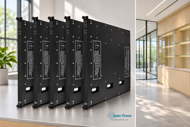
Product image is representative; revision or series may vary. Contact us to request a specific version.

Product Describe:

Emerson IC694MDL645 is a dc discrete input module. A single common group accepts positive- or negative-logic DC field signals.
  • Manufacturer part number
    IC694MDL645
  • Shipping
    Swift global dispatch
  • Condition
    New, original product
  • Shipping size (est.)
    3.5cm x 13.5cm x 13.5cm
  • Country of Origin
    USA
Get a quick price for IC694MDL645
E-mail *
Mobile
Company
Content *
Quantity *
Upload (gif, jpg, jpeg, png, bmp, doc, docx, xls, xlsx, ppt, pdf, csv)
For more information on how your data is processed and stored by Apterpower please read our privacy policy

What happens after you enquire

  • 0

    Review your reference

    Send the complete IC694MDL645 reference, label photographs and required quantity. Include the installed interface and hardware revision.

  • 1

    Confirm the offer

    Review the offered IC694MDL645 execution, New, original product condition and itemized accessories against the retained application.

  • 2

    Arrange dispatch

    Confirm quantity, dispatch date, lead-time start and delivery details in the quotation.

  • Match the complete marking

    Compare the full Emerson IC694MDL645 marking, hardware execution and mating interfaces with the installed position before approving a replacement.

  • Check the offered item before ordering

    Request clear photographs of the offered IC694MDL645 marking and connections. Ask the maintenance team to compare them with the applicable Emerson instructions and the installed circuit or system design.

Technical specifications for IC694MDL645

  • Manufacturer:
    Emerson
  • Product Category:
    PLC Systems
  • Spare Part Number:
    IC694MDL645
  • Weight:
    0.26 kg
  • Tariff Code:
    8537101190
  • Inputs:
    16 in one common group
  • Logic:
    Positive or negative
  • Input voltage:
    24 V DC nominal; 0–30 V DC
  • ON voltage:
    11.5–30 V DC
  • OFF voltage:
    0–5 V DC
  • Typical input current:
    7 mA at 24 V DC
  • Typical response:
    7 ms ON; 7 ms OFF
  • Backplane current:
    80 mA at 5 V, all inputs ON
  • Input current limits:
    3.2 mA minimum ON; 1.1 mA maximum OFF

Information

Overview Downloads Applications / Compatibility Product Precautions
  • The selected common polarity establishes how connected switches or sensors drive the input circuits; individual channels are not separate isolated groups.
Polarity arrangement: one common group for the selected sensor logic
Power boundary: distinguish logic supply from field excitation
Signal acceptance: compare leakage and pulse duration with input behavior
On an RX3i Universal Backplane, field use of the module’s 24 V connection requires the appropriate external isolated source at TB1. Powering the CPU and logic backplane does not by itself establish that source. The selected field-power arrangement also changes the applicable isolation boundary.

The input state must be evaluated against both sensor leakage and module switching thresholds. Status LEDs help locate a channel, but program timing still includes input response and the controller scan. Short events need a suitable input technology rather than an assumption that all discrete signals will be captured.

Retain input-address allocation and field supply when replacing an installed standard DC input module. Use the compatible common arrangement rather than assuming every sensor sources a positive voltage. An input that turns on at nominal voltage may remain on under leakage or fail near a reduced supply. Testing both conditions checks the interface margin.
Controller platform reference: PACSystems RX3i. Use the applicable installation instructions and approved system design.
Apter Power technical reference for IC694MDL645, covering the verified interface and operating limits. Installation topics include: identify the common reference; verify field excitation; test sensor leakage.
The Apter Power technical reference and installation guide cover complementary engineering and service topics.
Prepare Emerson IC694MDL645 for its configured installation using these checks.
Identify the common reference

Record whether the installed field circuit uses positive or negative logic. Label the shared common and each input before removing terminals.

Verify field excitation

Check the applicable external isolated supply and its return. On a Universal Backplane, confirm the required TB1 feed for the field 24 V arrangement.

Test sensor leakage

Measure the OFF condition at the input with the real sensor connected. Resolve excessive residual voltage or current before accepting the channel.


Compare raw state and logic

Exercise each input long enough to cover input response and the controller scan. Confirm that the correct raw bit changes before checking higher-level interlocks.

Restore the common-group record

Inspect the common terminal, channel assignments and field-power documentation. Remove test signals and release the process only after both electrical states are accepted.

Control the return to service

Keep the affected process in its approved maintenance state until field indications and the intended control or monitoring response have both been checked.

Alternative Names

Emerson IC694MDL645

Technical notes

Configuration scope: Technical values apply to IC694MDL645 with the stated operating conditions. Check supplied revision and the configured installation.

Engineering acceptance: The intended dc discrete input module function must be accepted with its actual mating interfaces and configured system. Measure the OFF condition at the input with the real sensor connected. Resolve excessive residual voltage or current before accepting the channel.

FAQ View All FAQ

  • Can IC694MDL645 mix unrelated sourcing and sinking circuits within its one common group?
    The common connection establishes the group reference. Each connected circuit must be compatible with that reference; do not treat the sixteen points as separately isolated polarity groups.
  • Why can a two-wire sensor prevent an IC694MDL645 input from turning off?
    Residual sensor current or voltage can exceed the module’s OFF-state limits. Evaluate the complete sensor circuit rather than checking nominal operating voltage alone.
  • What should be checked when IC694MDL645 logic is powered but field sensors have no excitation?
    Inspect the field source and, on an RX3i Universal Backplane, the external isolated supply connection at TB1. Logic power and the required field supply are separate paths.
  • How does using the auxiliary 24 V field output affect IC694MDL645 isolation?
    The applicable continuous isolation rating is reduced for that arrangement. Evaluate the complete circuit’s isolation requirement instead of applying the higher field-to-backplane figure unconditionally.
  • Is IC694MDL645 suitable for capturing every brief contact pulse?
    Its typical input response and the CPU scan both contribute to detection. Use a suitable fast input or counter when the required pulse is shorter than the reliable acquisition interval.
  • Why should IC694MDL645 be tested at both ON and OFF thresholds?
    An input that turns on at nominal voltage may remain on under leakage or fail near a reduced supply. Testing both conditions checks the interface margin.
  • What is required before an IC694MDL645 terminal block is reattached during permitted hot-swap service?
    Follow the approved RX3i procedure: the field terminal block is removed before module extraction or insertion and reinstalled afterward. Maintain process safeguards throughout the operation.
  • How can an IC694MDL645 channel LED disagree with a control action?
    The LED reflects the electrical input, while the program may add scan delay, interlocks or inversion. Trace the raw bit and logic path before changing the field wiring.
SPEAK TO OUR TEAM
Let’s find the right solution for you.
Send us the part number, quantity and delivery destination. Our team will help confirm availability and lead time.
  • Whatsapp: +86 18030235313

    Send us a message.
  • sales13@apterpower.com

    Complete our online form.
  • +86 18030235313

    Speak to our team in your native language.