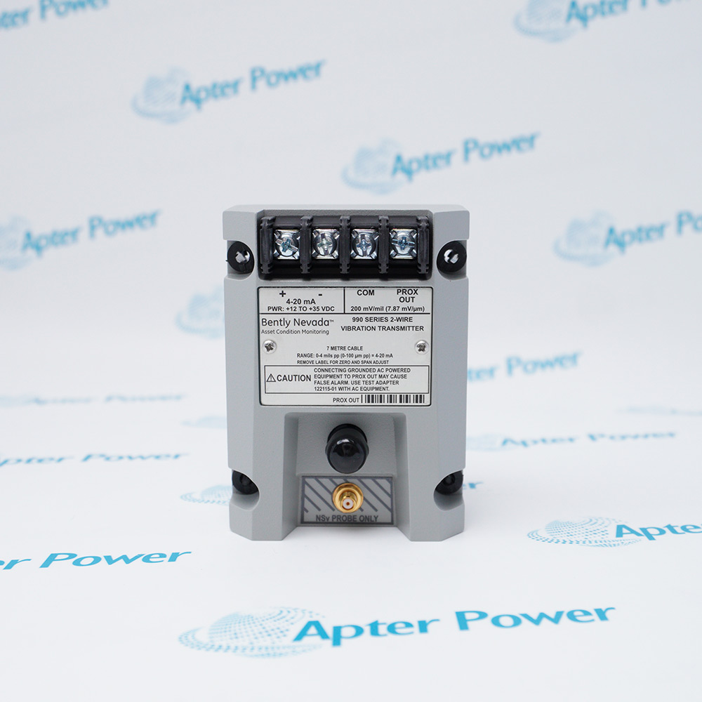
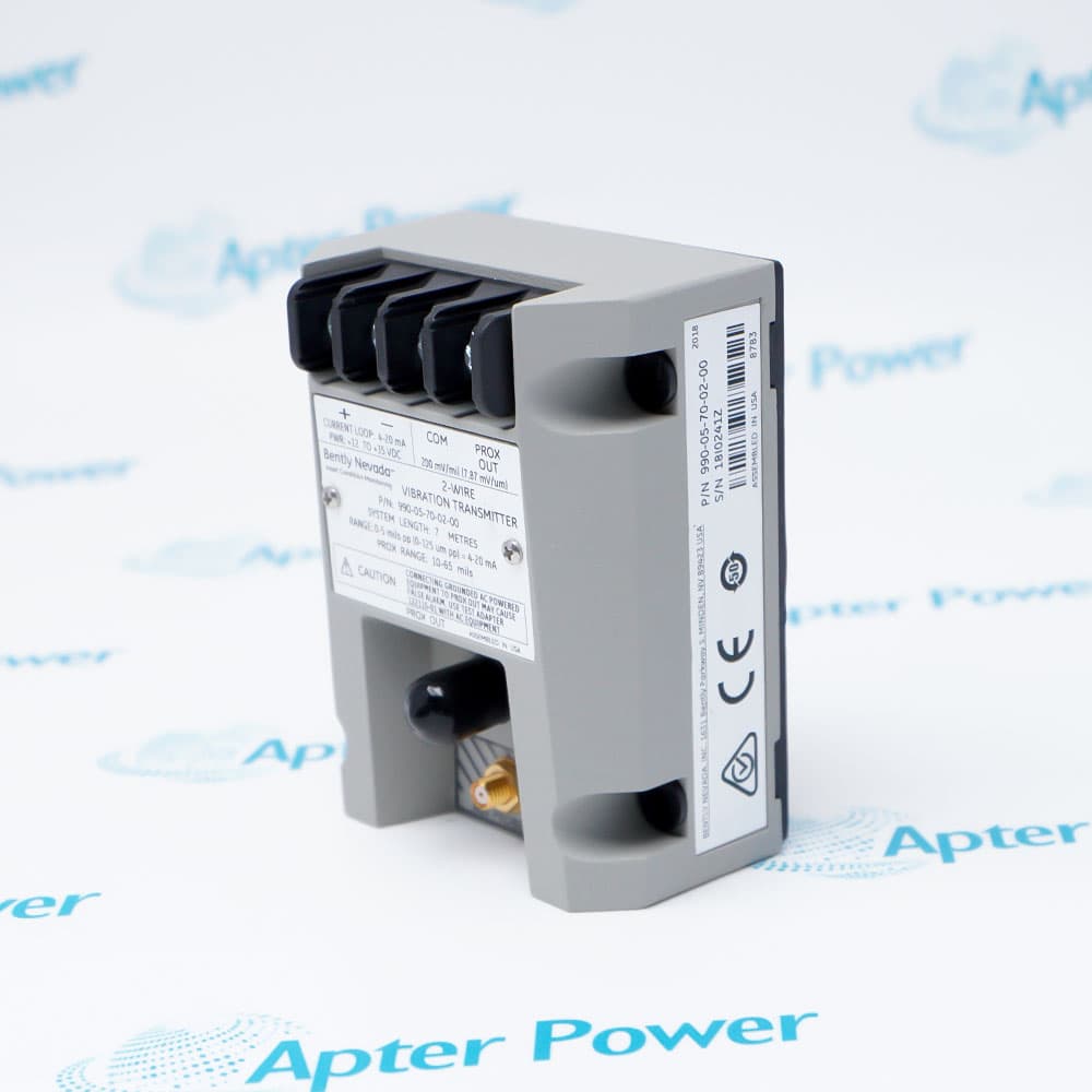
Product image is representative; revision or series may vary. Contact us to request a specific version.
Product Describe:
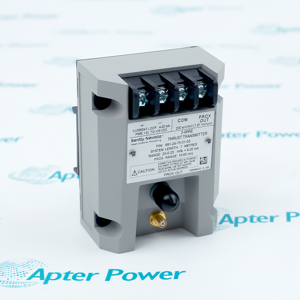
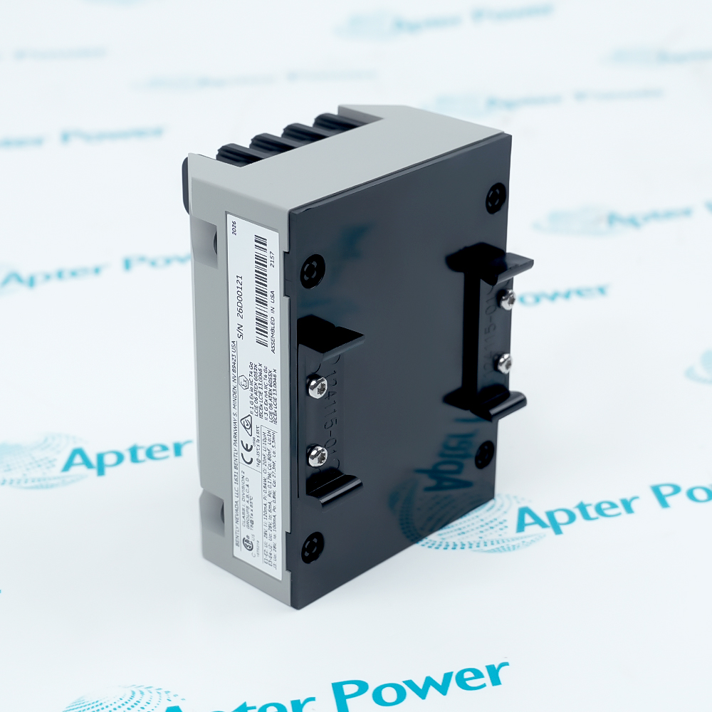
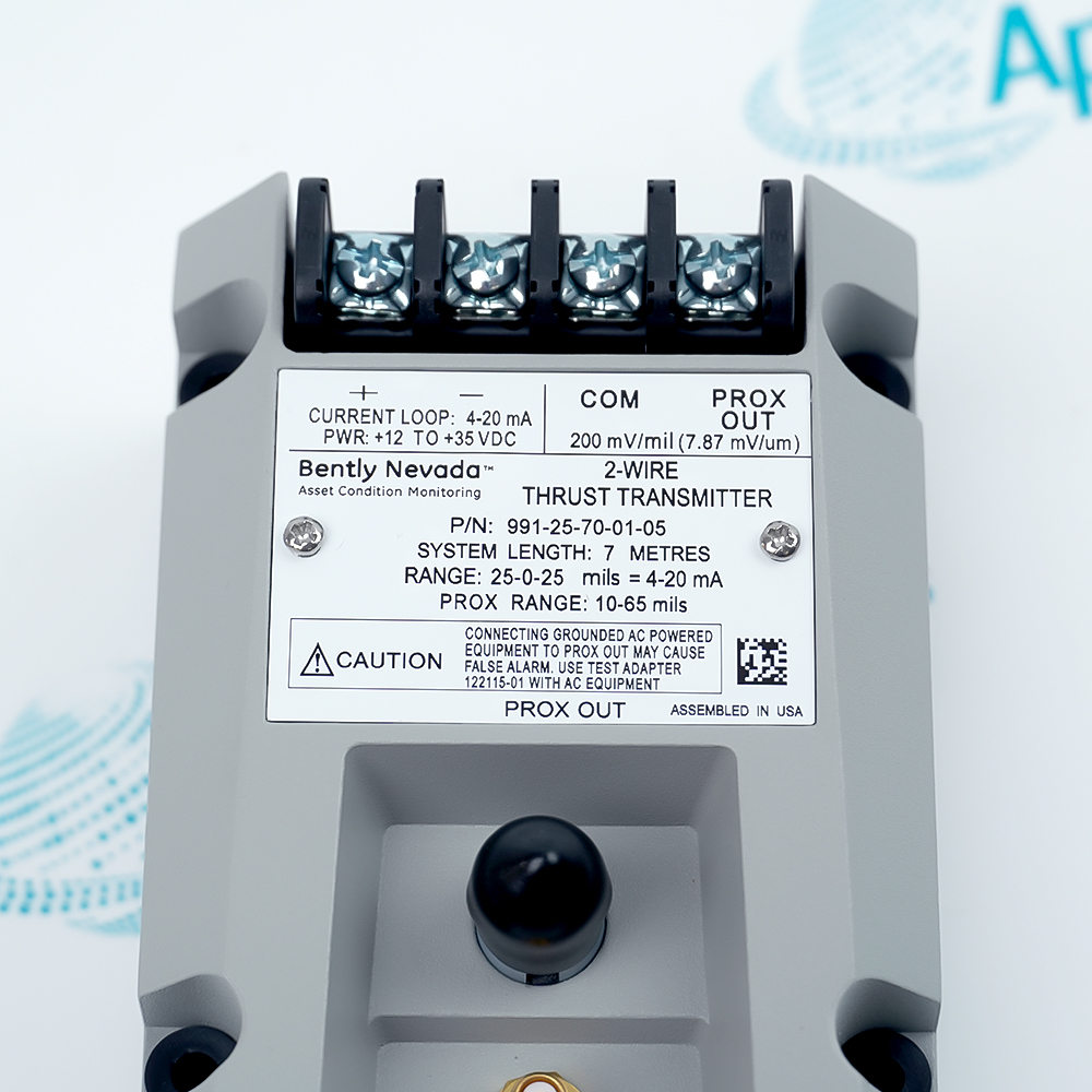
Bently Nevada 991-25-70-01-05 is a two-wire thrust transmitter with a 25-0-25 mil measurement range, a 7.0 m NSv transducer-system length and 35 mm DIN-rail mounting.
Bently Nevada 991-25-70-01-05 brings shaft axial-position monitoring into a control-system current loop, allowing the receiving system to perform its configured alarm and protection logic.
Includes the Proximitor function inside the transmitter.
Provides separate zero and span adjustments.
Offers a DC test-input connection for loop checks.
Suppresses erroneous high outputs when the probe signal becomes Not OK.
The PROX OUT terminals and coaxial connection expose dynamic and gap information for diagnostics. This diagnostic output is not isolated from the current loop, so grounded AC-powered instruments require an isolating test adapter.
Important Notice: Keep the initial probe gap clear of either end of the usable linear range.
The technical reference and field guide cover complementary aspects of this product. Select the document for the task being performed.

Compressor thrust trending
Measure axial displacement on centrifugal air-compressor shafts.
Pump position monitoring
Provide a proportional current input for a small-pump control system.
Motor or fan thrust channels
Connect a compatible NSv probe to a local machinery current loop.
Diagnostic access
Observe the buffered probe signal using correctly isolated test equipment.
Installation and service checks for Bently Nevada 991-25-70-01-05.
1
Use an NSv probe and cable combination with a total electrical length of 7.0 m.
2
Adjust probe gap so both directions of the thrust range remain measurable.
3
Supply +12 to +35 V DC at the transmitter terminals.
4
Check total loop resistance against the actual available supply voltage.
5
Use the zero and span adjustments without disturbing the mechanical probe setting.
6
Connect grounded AC-powered diagnostic instruments through the isolating test adapter.
7
Verify a Not OK fault is interpreted correctly by the receiving control system.
8
Test normal and counter-direction movement before enabling the machinery protection logic.
Technical notes
Verify the receiving system treats the sub-3.6 mA fault state separately from a valid thrust reading. Preserve isolation when adding diagnostic instruments to PROX OUT.
Why can incorrect probe gap prevent Bently Nevada 991-25-70-01-05 from reaching full scale?
A gap set too near either end of the usable probe range can exhaust the available travel in the normal or counter direction before the current loop reaches full scale.
How does Bently Nevada 991-25-70-01-05 signal a failed probe connection?
A Not OK condition drives the current below 3.6 mA within 100 microseconds; the signal returns within 0.1 s after the condition clears.
Can an earthed oscilloscope connect directly to Bently Nevada 991-25-70-01-05 PROX OUT?
Use the 122115-01 Test Adapter with grounded AC-powered instruments because PROX OUT is not isolated from the current loop.
What does the accuracy rating of Bently Nevada 991-25-70-01-05 actually cover?
The typical ±1.5% full-scale rating is measured from the TEST input to the voltage across a 250-ohm loop resistance.
When is a 1000-ohm loop load permissible for Bently Nevada 991-25-70-01-05?
The specified maximum of 1000 ohm, including cable resistance, applies with a 35 V DC supply.
Does Bently Nevada 991-25-70-01-05 require an external Proximitor unit?
No. The transmitter integrates the Proximitor function and accepts the matched NSv probe-and-extension assembly.
Can Bently Nevada 991-25-70-01-05 replace every rack-monitor protection function?
No. Functions such as Timed OK channel defeat, Danger Bypass and Trip Multiply are unavailable in this transmitter arrangement.
How can test-instrument loading affect PROX OUT on Bently Nevada 991-25-70-01-05?
PROX OUT has a 10-kilohm output impedance and is calibrated with a 10-megohm load. A lower-impedance instrument can load the diagnostic signal. Keep the diagnostic cable at or below 3 m and retain the required isolation arrangement.
Manufacturers
Supporting new and legacy automation
Whether you're maintaining existing equipment or sourcing parts for current systems, we provide fast, dependable supply you can rely on.
Please try to be as accurate as possible with your search.
We can quote you on 1000s of specialist parts, even if they are not listed on our website.