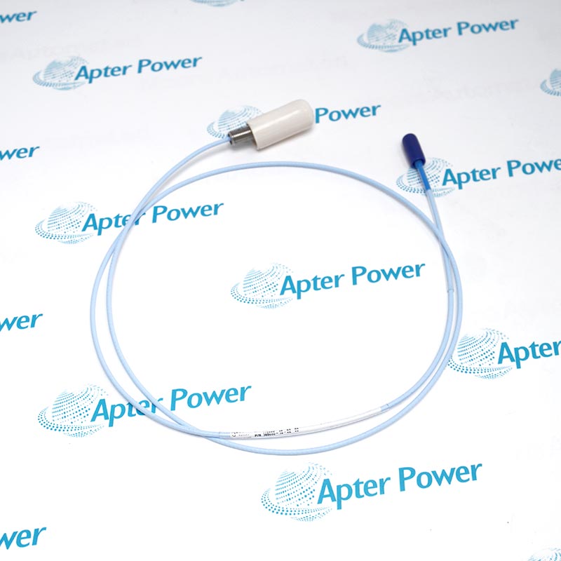
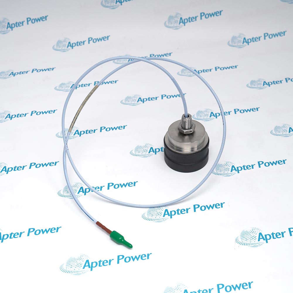
Technical specifications for 330103-00-25-05-02-00
-
Manufacturer:Bently Nevada
-
Product Category:Machinery Monitoring Systems
-
Spare Part Number:330103-00-25-05-02-00
-
Estimated shipping dimensions:1.8x1.6x105cm
-
Weight:0.12 kg
-
Tariff Code:8537101190
-
Counliy of origin:USA
-
Probe model:330103
-
Probe thread:M10 x 1
-
Armor:No
-
Unthreaded length:0 mm
-
Overall case length:250 mm
-
Total probe length:0.5 m (1.6 ft)
-
Connector:Miniature coaxial ClickLoc
-
Probe cable:Standard
-
Agency approval option:Not required
-
Power without barriers:-17.5 to -26 V DC; 12 mA maximum
-
Power with barriers:-23 to -26 V DC
-
Supply sensitivity:<2 mV/V
-
Output resistance:50 Ohm
-
Field-wire conductor range:0.2 to 1.5 mm2 (16 to 24 AWG)
-
Maximum field-wire length:305 m (1000 ft)
-
Linear range:2.0 mm (80 mils)
-
Linear-range limits:0.25 to 2.30 mm (10 to 90 mils)
-
Recommended radial-vibration gap:-9 V DC; approximately 1.27 mm (50 mils)
-
Incremental scale factor:7.87 V/mm (200 mV/mil)
-
Frequency response:0 to 10 kHz; +0/-3 dB
-
Extension-cable capacitance:69.9 pF/m typical
-
Minimum bend radius:25.4 mm (1.0 in)
Information
- Uses an M10 x 1 unarmored probe body
- Combines a 250 mm case with a half-metre lead
- Carries the signal through a miniature ClickLoc connector
- Supports the matched 3300 XL measurement chain
330103-00-25-05-02-00 operates with 3300 XL 8 mm Proximitor Sensor, matched extension cable when required, AISI 4140 steel target, compatible monitor input.
Engineered applications include Long-case radial vibration, Axial thrust position, Machine shaft centerline observation, Metric 8 mm loop renewal.
Important Notice: Verify the zero unthreaded length, 250 mm case, half-metre lead and bracket clearance before tightening; then match the total system length and set static gap.
Apter Power 330103-00-25-05-02-00 Manuals and Guides
Apter Power 330103-00-25-05-02-00 System and Technical Reference PDFBently Nevada 330103-00-25-05-02-00 Official Engineering Document PDFThe first document provides model-specific technical and system-reference information. The second is the directly related manufacturer document used for installation, configuration and engineering verification.
Long-case radial vibration
Reaches through an extended metric mounting bracket.
Axial thrust position
Measures axial shaft movement at a thrust collar.
Machine shaft centerline observation
Supports non-contact shaft-position trending.
Metric 8 mm loop renewal
Restores a documented short-lead 8 mm sensing point.
Verify the complete 330103-00-25-05-02-00 marking and M10 x 1 unarmored execution before work.
Place the monitored machine and protection channel in the approved maintenance state.
Protect the sensing tip, threads and mounting surface from impact, burrs and contamination.
Route and support the 0.5 m lead without sharp bends, crushing, tensile load or contact with moving parts.
Keep coaxial connector faces clean, dry and mechanically unloaded during handling.
Confirm the matched 3300 XL 8 mm electronics, total system length and target material before setting gap.
Preserve the documented probe separation and cable shielding arrangement during installation.
Prove gap voltage, polarity, dynamic response and alarm action before returning the channel to service.

Technical notes
FAQ View All FAQ
-
What is the documented system role of 330103-00-25-05-02-00?330103-00-25-05-02-00 is 3300 xl 8 mm m10 x 1 proximity probe. It is a metric 3300 XL 8 mm eddy-current probe that measures shaft-relative displacement for a matched Proximitor Sensor and monitoring channel.
-
Which host hardware must be matched with 330103-00-25-05-02-00?Match 330103-00-25-05-02-00 with the documented 3300 XL 8 mm Proximity Transducer System and the installed 3300 XL 8 mm Proximitor Sensor, matched extension cable when required.
-
How should the complete 330103-00-25-05-02-00 identification be verified?Compare the full marking with the controlling 141194 Rev. AM record; the documented probe model is 330103.
-
What connection check is required before installing 330103-00-25-05-02-00?Route and support the 0.5 m lead without sharp bends, crushing, tensile load or contact with moving parts.
-
How should 330103-00-25-05-02-00 be protected during handling?Keep coaxial connector faces clean, dry and mechanically unloaded during handling.
-
What configuration must be restored after replacing 330103-00-25-05-02-00?Confirm the matched 3300 XL 8 mm electronics, total system length and target material before setting gap.
-
What commissioning test is required for 330103-00-25-05-02-00?Prove gap voltage, polarity, dynamic response and alarm action before returning the channel to service.

-
Can 330103-00-25-05-02-00 replace a visually similar part directly?No direct substitution should be assumed. Match the complete 330103-00-25-05-02-00 code, interfaces, system length or mounting arrangement, and the approved host configuration.
Supporting new and legacy automation
-
Please try to be as accurate as possible with your search.
-
We can quote you on 1000s of specialist parts, even if they are not listed on our website.
-
We can't find any results for “”.
Related cases and sourcing guidance
View all case studiesYou May Also Like
Product Browsing History
-
Whatsapp: +86 18030235313
Send us a message. -
sales13@apterpower.com
Complete our online form. -
+86 18030235313
Speak to our team in your native language.