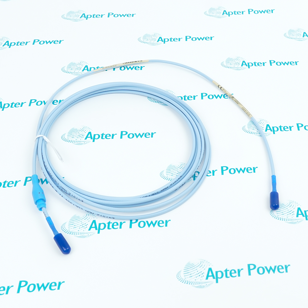
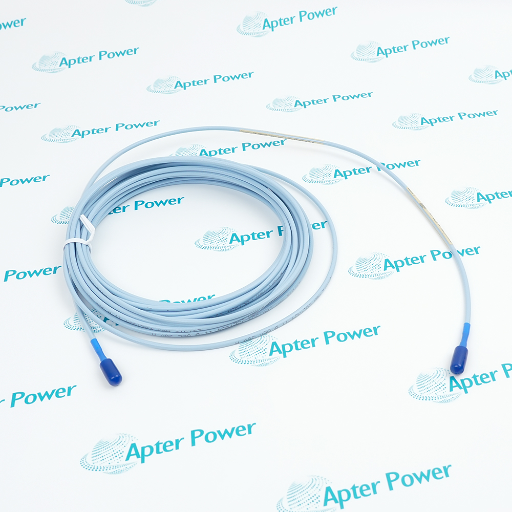
-
Match the complete marking
Compare the complete Bently Nevada 330851-02-000-050-10-00-05 marking, hardware configuration and connections with the installed item before approving a replacement.
-
Check the offered item before ordering
Request clear label and connector photographs of Bently Nevada 330851-02-000-050-10-00-05. Ask your maintenance team to compare the offered item with the installed equipment and the applicable Bently Nevada 3300 XL 25 mm Proximity Transducer System, 163236 Rev. M before ordering.
Technical specifications for 330851-02-000-050-10-00-05
-
Manufacturer:Bently Nevada
-
Product Category:Machinery Monitoring Systems
-
Spare Part Number:330851-02-000-050-10-00-05
-
Weight:0.36 kg
-
Tariff Code:8537101190
-
Transducer family:3300 XL 25 mm
-
Mounting thread:M30×2
-
Overall case length:50 mm
-
Unthreaded-length selection:0 mm
-
Total probe lead:1.0 m
-
Lead armor:None
-
Probe resistance, center to outer:6.2 ± 0.5 Ω
-
Probe tip / case material:PEEK / AISI 304 stainless steel
-
Cable construction:75 Ω triaxial, PFA-insulated FluidLoc
-
Matched-system scale factor:0.787 V/mm nominal
-
Matched-system linear range:12.7 mm under specified calibration conditions
-
Probe continuous temperature:-35 to +200 °C
Information
- Bently Nevada 330851-02-000-050-10-00-05 supports non-contact observation of rotor growth relative to the turbine casing. The medium-reach threaded case supports collar or ramp observation where target material and available sensing surface determine whether the nominal system response can be used.
Integral lead: 1.0 m unarmored FluidLoc cable
Matched-system output: 0.787 V/mm nominal
The 1 m probe lead combines with the appropriate 4 m or 8 m extension cable to form a 5 m or 9 m system using the matching 3300 XL 25 mm Proximitor Sensor. Disconnected probe resistance from center to outer conductor is 6.2 ± 0.5 Ω. Cable and conditioner selection must preserve the complete electrical length.
For the complete matched system, nominal sensitivity is 0.787 V/mm and the linear range is 12.7 mm. The reference conditions include a -24 Vdc supply, a 10 kΩ load, a Bently Nevada AISI 4140 steel target at least 61 mm in diameter, a 7 mm gap and component temperatures from 0 to +45 °C. Probe survivability to +200 °C does not make these reference accuracy conditions universal.
330851-02-000-050-10-00-05 Original Technical Excerpt
Original Bently Nevada pages explain the 25 mm sensing system, calibrated response, materials and applicable cable options. PDF · 6 pages.330851-02-000-050-10-00-05 Installation & Verification Guide
Apter Power field guide covering target and approval assessment, connector protection and displacement verification. PDF · 5 pages.
Application scope: Differential-expansion performance depends on the collar or ramp geometry, target material and configured channel arrangement. Mechanical fit alone does not establish electrical or calibration compatibility.
Target and approval assessment
Check the AISI 4140 calibration basis, collar surface and actual multiple-approval markings for the intended installation.Turbine collar observation
Measure differential rotor-to-casing growth with a correctly aligned and gapped matched transducer chain.Complementary DE channels
Use opposing collar faces only with the intended two-channel arrangement and corresponding monitor configuration.Controlled displacement verification
Move the probe mounting relative to the target and compare the electrical indication with a mechanical movement reference.
The 1 m probe lead combines with the appropriate 4 m or 8 m extension cable to form a 5 m or 9 m system using the matching 3300 XL 25 mm Proximitor Sensor.
Keep the high-temperature ClickLoc connector clean, finger tight and inside its connector protector.
Use the intended collar or ramp surface and verify the target material against the calibration.
Do not apply probe-body tightening torque to the electrical connector; connector maximum is 0.565 N·m.
Apply probe, cable and Proximitor Sensor temperature limits separately; avoid treating short-term exposure as continuous service.
Test the complete channel through controlled relative movement before restoring the machine protection function.
Alternative Names
Technical notes
Electrical relationship: The 1 m probe lead combines with the appropriate 4 m or 8 m extension cable to form a 5 m or 9 m system using the matching 3300 XL 25 mm Proximitor Sensor. Disconnected probe resistance from center to outer conductor is 6.2 ± 0.5 Ω. Cable and conditioner selection must preserve the complete electrical length.
Measurement boundary: For the complete matched system, nominal sensitivity is 0.787 V/mm and the linear range is 12.7 mm. The reference conditions include a -24 Vdc supply, a 10 kΩ load, a Bently Nevada AISI 4140 steel target at least 61 mm in diameter, a 7 mm gap and component temperatures from 0 to +45 °C. Probe survivability to +200 °C does not make these reference accuracy conditions universal.
Technical reference: Bently Nevada 3300 XL 25 mm Proximity Transducer System, 163236 Rev. M.

FAQ View All FAQ
-
Which target material underlies the standard calibration for 330851-02-000-050-10-00-05?The standard matched system is calibrated to Bently Nevada AISI 4140 steel. Accuracy and interchangeability limits do not automatically apply to a different target material; a different calibration must be selected deliberately.
-
Why does 330851-02-000-050-10-00-05 need a target large enough to cover the sensing field?The specified flat target is at least 61 mm in diameter. A smaller target or an unsuitable collar geometry can change the response, so the available target surface must be checked before applying the stated system performance.
-
What cable construction protects the signal path of 330851-02-000-050-10-00-05?The probe uses 75 Ω triaxial FluidLoc cable with PFA insulation. The 00 armor option provides no stainless-steel armor, so the routing must protect the lead from mechanical damage.
-
Can a 50 mm case on 330851-02-000-050-10-00-05 be treated as its sensing range?No. The 50 mm value describes the case geometry. The nominal linear measurement range of the matched 25 mm transducer system is 12.7 mm under its stated conditions.
-
How tightly should the connector on 330851-02-000-050-10-00-05 be assembled?The connector-to-connector joint is finger tight, with a maximum torque of 0.565 N·m. Do not apply the much larger threaded-case torque to the electrical connector.
-
What changes when two probes like 330851-02-000-050-10-00-05 view opposite sides of a collar?A complementary-input arrangement can approximately double the measurable differential-expansion range. It requires the appropriate two-channel geometry and monitor configuration rather than simply reversing one probe signal.
-
Does the 05 approval option on 330851-02-000-050-10-00-05 establish suitability for every hazardous area?No. The option selects multiple approvals, but the actual markings, entity parameters and installation drawings must match the area and complete system. A suffix alone does not approve an arbitrary installation.
-
How does temperature affect the accuracy assessment for 330851-02-000-050-10-00-05?The principal accuracy limits use the stated calibration conditions. Over the specified extended-temperature combinations, deviation from the best-fit straight line can increase to ±0.92 mm; apply the relevant probe, cable and sensor temperatures together.
Supporting new and legacy automation
-
Please try to be as accurate as possible with your search.
-
We can quote you on 1000s of specialist parts, even if they are not listed on our website.
-
We can't find any results for “”.
You May Also Like
Product Browsing History
-
Whatsapp: +86 18030235313
Send us a message. -
sales13@apterpower.com
Complete our online form. -
+86 18030235313
Speak to our team in your native language.