-
Match the complete marking
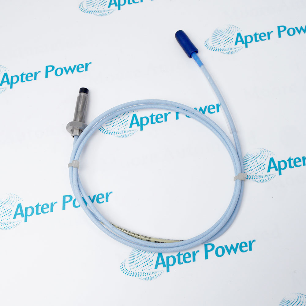
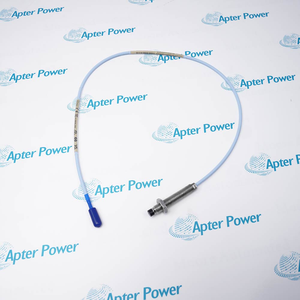
Send photographs of the full 330173-04-08-10-02-00 marking, probe case and connector together with the required quantity and installed holder details.
-
Check the offered item before ordering
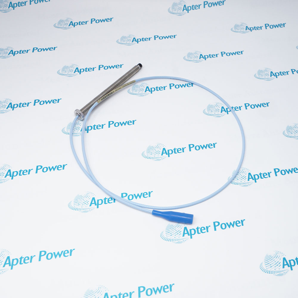
Compare the offered M8 x 1 thread, 80 mm case, 40 mm unthreaded reach and 1.0 m lead with the installed channel and applicable manufacturer instructions before ordering.
Technical specifications for 330173-04-08-10-02-00
-
Manufacturer:Bently Nevada
-
Product Category:Machinery Monitoring Systems
-
Spare Part Number:330173-04-08-10-02-00
-
Weight:0.04 kg
-
Tariff Code:8537101190
-
Mounting thread:M8 x 1
-
Unthreaded length:40 mm
-
Overall case length:80 mm
-
Total probe length:1.0 m
-
Termination:Miniature coaxial ClickLoc; standard cable
-
Sensing tip diameter:5 mm
-
Probe cable impedance:75 ohm, FEP-insulated triaxial
-
Probe resistance at 1 m:7.59 ±0.50 ohm, center to outer conductor
-
Matched-system linear range:2 mm; approximately 0.25–2.3 mm gap
-
Nominal system sensitivity:7.87 V/mm (200 mV/mil)
-
Recommended operating gap:1.27 mm (50 mils)
-
System frequency response:DC–10 kHz, +0 / -3 dB
-
Probe temperature range:-35 to +177 °C
Information
- Bently Nevada 330173-04-08-10-02-00 provides a metric mounting arrangement with extended smooth reach, allowing the sensing tip to project beyond the threaded support.
Probe case: 80 mm overall length, without armor
Connection: 1.0 m standard cable; miniature coaxial ClickLoc
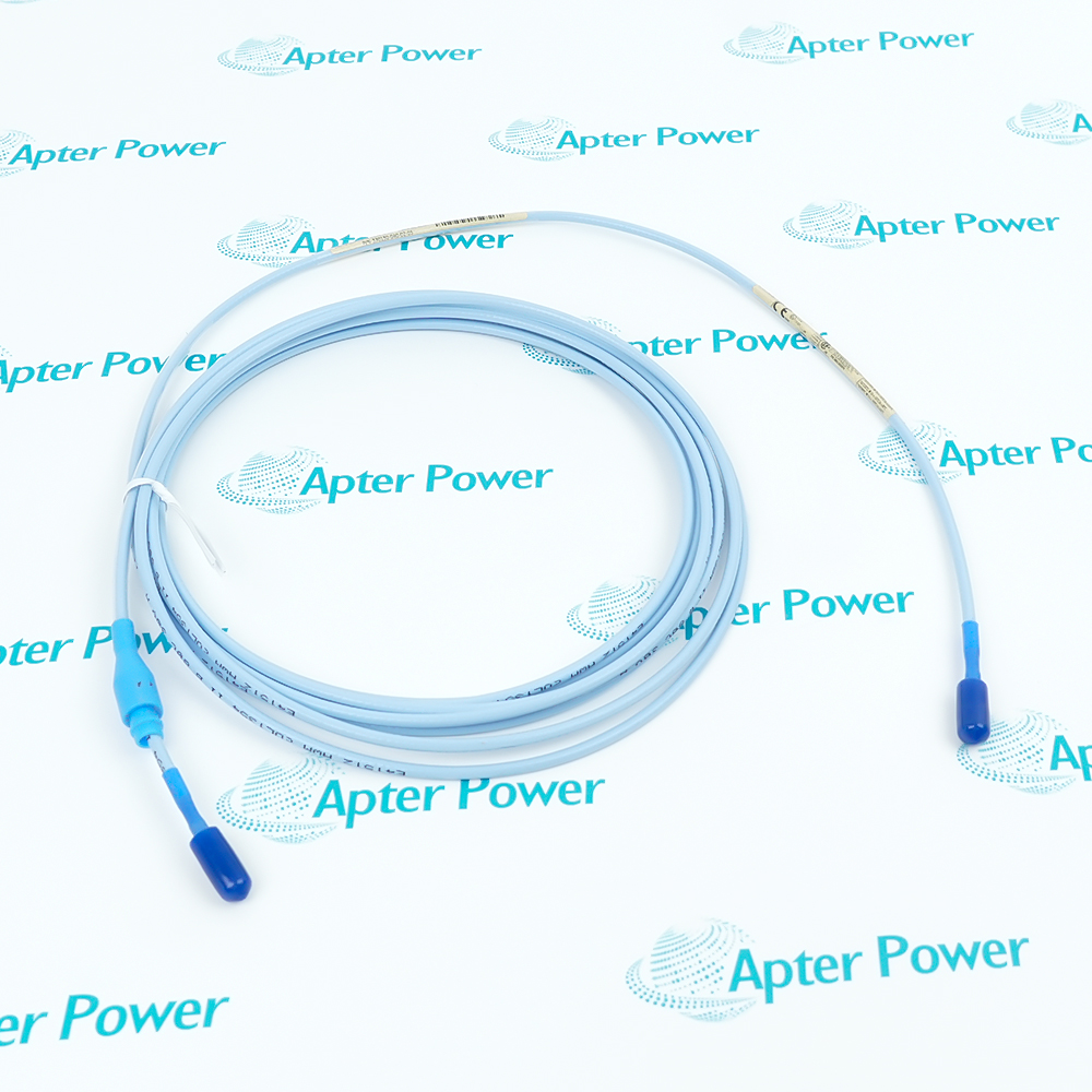
The probe, compatible XL extension cable and XL Proximitor Sensor form one measurement chain. Total probe and extension-cable length must match the conditioner; the complete system provides a nominal 7.87 V/mm response over a 2 mm linear range under the specified calibration conditions.
A standard 1.0 m lead and option 02 ClickLoc termination are fitted to this configuration. The coaxial joint requires suitable environmental protection. The PPS tip and stainless-steel case support non-contact shaft measurements, while target material, gap and nearby metal remain part of the measurement setup.
330173-04-08-10-02-00 Official Datasheet Excerpt
Technical data for the 3300 5 mm system applicable to 330173-04-08-10-02-00, including operating limits and probe construction. PDF · 6 pages.330173-04-08-10-02-00 Installation & Verification Guide
Apter Power field guide for the selected M8 x 1 probe geometry, signal-chain preparation and functional verification. PDF · 5 pages.
Application scope: Applications depend on a conductive target, correct probe location and a receiving channel configured for the required vibration, position or timing function.
Radial shaft vibration
Measure changing shaft-to-probe distance on fluid-film bearing machines using a suitable radial mounting position.Axial position
Observe thrust-surface movement with adequate target area and clearance between adjacent probes.Constrained mechanical access
Use the 80 mm case and 40 mm smooth section where the holder geometry requires this particular reach and thread.Speed and phase reference
Detect a suitable shaft feature with the appropriate monitoring input and application-specific target arrangement.
Use a matching M8 x 1 holder and limit engagement to 12 mm; check adjustment without forcing the case.
Keep the sensing tip clear of the target through the complete expected movement and thermal-growth range.
Preserve at least 25.4 mm bend radius and provide strain relief at the probe lead and connection.
Verify probe and extension lengths against the Proximitor Sensor before connecting the monitor.
Protect the standard ClickLoc joint from moisture; do not assume option 02 includes a connector protector.
Check DC gap and controlled target response through the receiving channel before restoring machine protection.
Alternative Names
Technical notes
Calibration boundary: The sensitivity and linearity values apply to a complete matched chain with the specified AISI 4140 target and calibration conditions.
Small-tip clearance: The 5 mm package does not authorize reduced side-view clearance or closer tip spacing than the 8 mm arrangement.
Cable construction: Standard cable is fitted; oil-blocking performance is not an attribute of connector option 02.

FAQ View All FAQ
-
What mounting geometry is selected by 04-08 on 330173-04-08-10-02-00?The probe has 40 mm unthreaded length and an 80 mm overall case. Its M8 x 1 thread provides metric mounting; the remaining nominal threaded section is 40 mm.
-
Can 330173-04-08-10-02-00 be screwed into a 1/4-28 probe holder?No. M8 x 1 and 1/4-28 UNF are different thread forms and pitches. Use the matching metric mounting arrangement and do not force the probe into an imperial holder.
-
What bend radius should be retained around the lead of 330173-04-08-10-02-00?The minimum cable bend radius is 25.4 mm. Allow sufficient routing space beyond the case so the lead is not sharply bent, pulled against an edge or loaded by the connector joint.
-
How does the PPS tip on 330173-04-08-10-02-00 support the sensing element?The polyphenylene sulfide tip encloses the probe coil, and the TipLoc molding construction bonds the tip to the body. It remains a sensing surface that must be protected from contact with the rotating target.
-
What separates the 10 kHz response of 330173-04-08-10-02-00 from an alarm setting?DC–10 kHz describes the matched transducer response at +0/-3 dB under the stated wiring conditions. Alarm bandwidth and threshold are separate settings of the receiving monitoring channel.
-
Does the 1 m lead on 330173-04-08-10-02-00 define the complete system length?No. The 10 code specifies the probe total length. The probe plus compatible extension cable must equal the selected 5 m or 9 m Proximitor system length.
-
How deeply can the M8 thread of 330173-04-08-10-02-00 engage the mounting hole?The maximum thread engagement is 12 mm. This is independent of the available threaded case length; excessive engagement can cause binding during adjustment.
-
Why should two axial probes near 330173-04-08-10-02-00 be checked for cross-talk?Their electromagnetic fields can interact. For the stated 5 mm system conditions, maintain at least 40 mm tip separation for axial measurements; shaft geometry and operating gap also influence interaction.
Supporting new and legacy automation
-
Please try to be as accurate as possible with your search.
-
We can quote you on 1000s of specialist parts, even if they are not listed on our website.
-
We can't find any results for “”.
You May Also Like
Product Browsing History
-
Whatsapp: +86 18030235313
Send us a message. -
sales13@apterpower.com
Complete our online form. -
+86 18030235313
Speak to our team in your native language.