Speak to a sourcing specialist
sales13@apterpower.com
Get a quick price for 330173-00-03-10-02-CN
E-mail *
Mobile *
Company
Content *
Quantity *
Upload (gif, jpg, jpeg, png, bmp, doc, docx, xls, xlsx, ppt, pdf, csv)
For more information on how your data is processed and stored by Apterpower please read our privacy policy

What happens after you enquire

  • 1

    Requirement review

    We review the part number, quantity and delivery requirements and ask for any missing details.
  • 2

    Quotation and availability

    We confirm the proposed item, condition, availability, price and estimated lead time in the quotation.
  • 3

    Order confirmation and dispatch

    Once the quotation and purchasing details are agreed, your contact will coordinate the order and available dispatch information.

Technical specifications for 330173-00-03-10-02-CN

  • Manufacturer:
    Bently Nevada
  • Product Category:
    Machinery Monitoring Systems
  • Spare Part Number:
    330173-00-03-10-02-CN
  • Estimated shipping dimensions:
    115.5×1.5×1.5cm
  • Weight:
    0.04 kg
  • Tariff Code:
    8537101190
  • Counliy of origin:
    USA
  • Sensing tip:
    5 mm
  • Mounting thread:
    M8 x 1
  • Unthreaded length:
    0 mm
  • Overall case length:
    30 mm
  • Integral cable length:
    1.0 m
  • Probe cable:
    75 Ω triaxial, FEP insulation
  • Cable protection:
    Unarmored
  • Connection:
    Miniature coaxial ClickLoc, standard cable
  • Probe case:
    AISI 303 or 304 stainless steel
  • Probe tip:
    PPS
  • Compatible assembled system lengths:
    5 m or 9 m, including extension cable
  • Nominal system scale factor:
    7.87 V/mm (200 mV/mil), subject to specified system conditions
  • Typical system linear range:
    2 mm

Information

Overview Manuals Common Applications Product Precautions
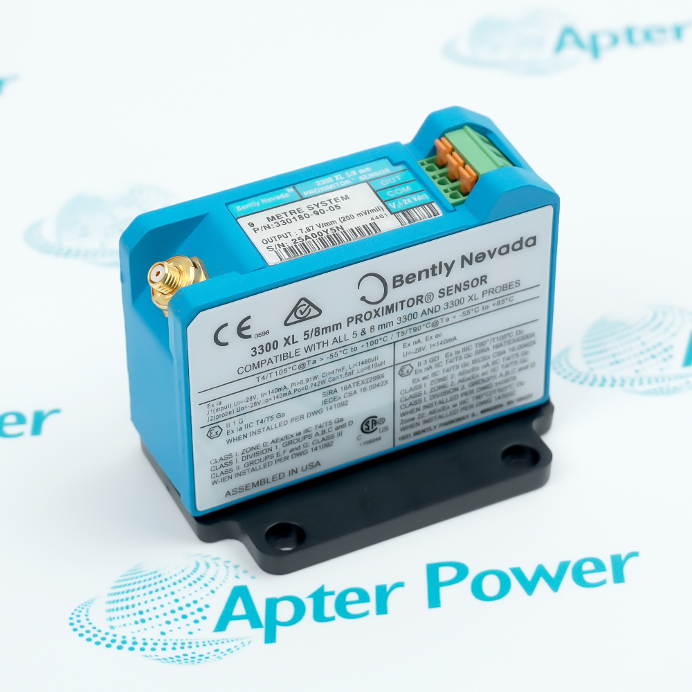
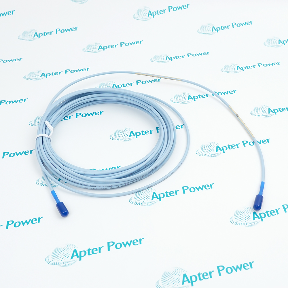
Bently Nevada 330173-00-03-10-02-CN suits a constrained mounting position where a small probe body is needed, such as a location between thrust-bearing pads.
  • Uses a compact 30 mm case with no unthreaded section.
  • Joins to the extension cable through a locking miniature coaxial connector.
  • Uses TipLoc molding to bond the sensing tip to the probe body.
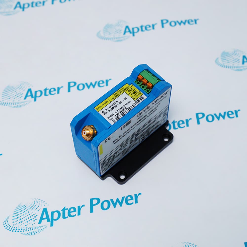
  • Produces both static-position and dynamic-vibration information through its matched conditioner.

The smaller tip does not reduce the side-view or tip-spacing requirements of the 8 mm system. Leave the electrical clearance dictated by the transducer arrangement rather than choosing a closer spacing solely from the probe body diameter.

Important Notice: Keep the selected sensor and extension cable associated with their electrical system length; do not transfer the performance limits of an all-XL 8 mm system to this 5 mm probe channel.

Bently Nevada 330173-00-03-10-02-CN Manuals & Downloads
Bently Nevada 330173-00-03-10-02-CN Official Technical Reference Excerpt (PDF)Bently Nevada 330173-00-03-10-02-CN Installation & Commissioning Guide (PDF)

The technical excerpt covers transducer construction and performance. The installation guide develops mounting, connection and signal-verification procedures for the selected assembly.


Constrained thrust measurement
Place a small sensing body at a conductive thrust target.
Fluid-film bearing monitoring
Acquire displacement where the mounting arrangement favors a 5 mm probe.
Speed-reference sensing
Observe target passages through an appropriately configured measurement channel.
Static clearance tracking
Follow the average probe-to-target distance separately from its vibration component.
Protect the measuring target, cable path and electrical connections when installing Bently Nevada 330173-00-03-10-02-CN.
1
Verify the M8 x 1 mounting thread before inserting the case.
2
Check that the 30 mm case reaches the target without stressing the lead.
3
Retain the required metal clearance around the sensing tip.
4
Identify the complete five- or nine-metre electrical arrangement.
5
Protect the cable junction for its actual oil and moisture exposure.
6
Avoid using a different target alloy as an unqualified calibration substitute.
7
Sweep displacement with the matched conditioner and monitor connected.
8
Confirm that the restored channel represents the intended shaft position.

Technical notes

A 1.0 m probe has a nominal DC resistance of 7.59 ± 0.50 Ω. Use the disconnected probe for this check and treat continuity as a preliminary check before displacement calibration.

FAQ View All FAQ

  • Does the 30 mm case of 330173-00-03-10-02-CN permit 30 mm of threaded engagement?
    No. Maximum M8 x 1 thread engagement is 12 mm with the matching internal thread fit. Excess engagement can cause binding even though the nominal thread size is correct.
  • Which field cable is recommended between the conditioner used with 330173-00-03-10-02-CN and the monitor?
    Use a shielded three-conductor triad in the 16–24 AWG range. This field cable carries the conditioned signal and is distinct from the calibrated probe extension cable.
  • How does probe temperature affect the displacement accuracy of 330173-00-03-10-02-CN?
    Across -35 to +177 °C, the typical incremental scale factor remains within ±10% of 7.87 V/mm and straight-line deviation within ±0.076 mm. These limits differ from the room-temperature figures.
  • Does the smaller sensing body of 330173-00-03-10-02-CN allow closer surrounding metal?
    No. The 5 mm package helps with physical mounting space but does not reduce the side-view clearances or tip-separation requirements of the 8 mm system.
  • How is incremental scale factor evaluated for a system using 330173-00-03-10-02-CN?
    It is measured in 0.25 mm displacement increments across the linear range. The nominal value is 7.87 V/mm with a typical ±6.5% tolerance including interchangeability error under the reference conditions.
  • What bandwidth can the conditioned signal from 330173-00-03-10-02-CN support over the specified field wiring?
    The system frequency response is 0–10 kHz at +0/-3 dB with up to 305 m of field wiring. Longer wiring or remote barriers require assessment of high-frequency signal roll-off.
  • How far apart should two 330173-00-03-10-02-CN sensing tips be to limit cross-talk?
    Typical minimum separation is 40 mm for axial position or 38 mm for radial vibration. Target diameter and operating gap also matter; the cross-talk guidance assumes the specified shaft and gap conditions.
  • Why does the pressure seal of 330173-00-03-10-02-CN need extra attention near its low-temperature limit?
    Although the probe range starts at -35 °C, exposure below -34 °C may cause premature pressure-seal failure. The probe is not pressure-tested before shipment, so the application must provide appropriate fluid and gas containment.
Related reading

Related cases and sourcing guidance

View all case studies
SPEAK TO OUR TEAM
Let’s find the right solution for you.
Send us the part number, quantity and delivery destination. Our team will help confirm availability and lead time.
  • Whatsapp: +86 18030235313

    Send us a message.
  • sales13@apterpower.com

    Complete our online form.
  • +86 18030235313

    Speak to our team in your native language.