Speak to a sourcing specialist
sales13@apterpower.com
Get a quick price for 330104-00-08-15-02-00
E-mail *
Mobile *
Company
Content *
Quantity *
Upload (gif, jpg, jpeg, png, bmp, doc, docx, xls, xlsx, ppt, pdf, csv)
For more information on how your data is processed and stored by Apterpower please read our privacy policy

What happens after you enquire

  • 1

    Requirement review

    We review the part number, quantity and delivery requirements and ask for any missing details.
  • 2

    Quotation and availability

    We confirm the proposed item, condition, availability, price and estimated lead time in the quotation.
  • 3

    Order confirmation and dispatch

    Once the quotation and purchasing details are agreed, your contact will coordinate the order and available dispatch information.

Technical specifications for 330104-00-08-15-02-00

  • Manufacturer:
    Bently Nevada
  • Product Category:
    Machinery Monitoring Systems
  • Spare Part Number:
    330104-00-08-15-02-00
  • Estimated shipping dimensions:
    123.3×1.7×2cm
  • Weight:
    0.16 kg
  • Tariff Code:
    8537101190
  • Counliy of origin:
    USA
  • Transducer family:
    3300 XL 8 mm
  • Mounting thread:
    M10 x 1
  • Lead protection:
    Stainless-steel armor
  • Unthreaded length:
    0 mm
  • Case length:
    80 mm
  • Probe length:
    1.5 m
  • Connector:
    ClickLoc without connector protector
  • Approvals:
    Not required

Information

Overview Manuals Common Applications Product Precautions
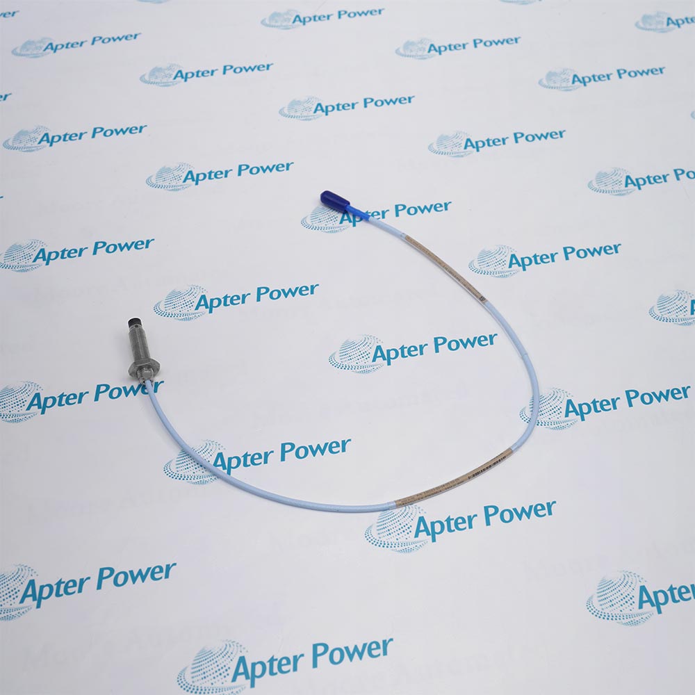
Bently Nevada 330104-00-08-15-02-00 combines a fully threaded metric case and armored lead for a 1.5 m 3300 XL 8 mm sensing path.
  • Uses the armored 330104 metric probe construction.
  • Provides a fully threaded 80 mm M10 x 1 case.
  • Carries a 1.5 m standard cable inside the armor assembly.
  • Ends in the code-02 ClickLoc termination without a protector.

The fully threaded case provides mounting adjustment across the available thread engagement. Secure the armor and lead so they cannot transmit vibration or pull into the probe body.

Important Notice: Match the complete 330104-00-08-15-02-00 marking before removing the installed probe. Verify proportional voltage response, polarity and channel indication before returning the machine to service.

Bently Nevada 330104-00-08-15-02-00 Manuals & Downloads
Bently Nevada 330104-00-08-15-02-00 Official Technical Reference Excerpt (PDF)Bently Nevada 330104-00-08-15-02-00 Installation & Commissioning Guide (PDF)

The first document covers the product function, system role and technical selection. The installation guide covers identification, connection checks, commissioning and the acceptance record.


Shaft-relative vibration
Uses the installed probe position to observe dynamic shaft motion in metric armored probe positions.
Static position
Supports non-contact measurement of shaft position inside the calibrated transducer-system range.
Machine protection input
Feeds the matched Proximitor sensor and monitoring channel used for alarms and protection logic.
Commissioning verification
Allows gap, signal response and channel direction to be checked after installation.
Before installing Bently Nevada 330104-00-08-15-02-00, confirm the documented system, interfaces and controlled configuration.
1
Match the complete 330104-00-08-15-02-00 marking before removing the installed probe.
2
Confirm the mounting interface is M10 x 1 and that the case provides adequate thread engagement.
3
Keep the probe, extension cable and Proximitor sensor at the documented matched 3300 XL 8 mm system electrical length.
4
Protect the probe tip, coaxial lead and ClickLoc connector from impact, contamination and sharp bends.
5
Route the lead away from hot surfaces, rotating parts and locations that can crush or abrade the cable.
6
Use the connector protector only when it is included in the complete ordering code.
7
Set the probe gap with the matched system and the controlled target material before enabling protection.
8
Verify proportional voltage response, polarity and channel indication before returning the machine to service.

Technical notes

Match the complete 330104-00-08-15-02-00 marking before removing the installed probe. Verify proportional voltage response, polarity and channel indication before returning the machine to service.

FAQ View All FAQ

  • Which part of 330104-00-08-15-02-00 is armored?
    The 330104 construction adds stainless-steel armor to the probe lead.
  • What case profile is specified by 00-08 in 330104-00-08-15-02-00?
    It is a fully threaded case with 0 mm unthreaded length and 80 mm overall length.
  • How much cable is integral to 330104-00-08-15-02-00?
    The 15 option specifies 1.5 m total probe length.
  • Does 330104-00-08-15-02-00 have the ClickLoc protector?
    No. Connector code 02 omits the protector.
  • Which approval package is selected on 330104-00-08-15-02-00?
    The terminal 00 means the agency-approval option is not required.
  • How should the armor on 330104-00-08-15-02-00 be restrained?
    Support it independently so bending or vibration loads are not transferred to the case or connector.
  • What thread must be prepared for 330104-00-08-15-02-00?
    Use a clean M10 x 1 mounting thread with adequate engagement and target clearance.
  • What proves the signal path after fitting 330104-00-08-15-02-00?
    A controlled gap change must produce the expected voltage and monitor response across the matched system.
Related reading

Related cases and sourcing guidance

View all case studies
SPEAK TO OUR TEAM
Let’s find the right solution for you.
Send us the part number, quantity and delivery destination. Our team will help confirm availability and lead time.
  • Whatsapp: +86 18030235313

    Send us a message.
  • sales13@apterpower.com

    Complete our online form.
  • +86 18030235313

    Speak to our team in your native language.