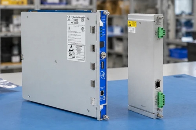
-
Match the complete marking
Include the complete 21000-34-05-15-029-04-02 reference and compare the installed housing, sleeve, probe and mounting arrangement.
-
Check the offered item before ordering
Request label and assembly photographs. Have your maintenance team compare the offered 21000-34-05-15-029-04-02 with the installed housing and applicable Bently Nevada probe-housing instructions.
Technical specifications for 21000-34-05-15-029-04-02
-
Manufacturer:Bently Nevada
-
Product Category:Machinery Monitoring Systems
-
Spare Part Number:21000-34-05-15-029-04-02
-
Weight:1.1 kg
-
Tariff Code:8537101190
-
Housing body:Aluminum
-
Probe sleeve:304 stainless steel
-
Probe selection:3300 XL 8 mm, reverse mount
-
Probe lead length:0.5 m
-
Standoff selection:1.5 in / 38.1 mm
-
Nominal penetration:2.9 in / 73.66 mm
-
Combined C+D:4.4 in / 111.76 mm
-
Mounting thread:3/4-14 NPT
-
Fitting selection:One 3/4-14 NPT plug only
-
Connector protector:Included in probe selection
-
Cover construction:Threaded dome cover
-
Sealing components:O-rings and thread seal
-
Probe operating/storage range:−51 to +177 °C; pressure-seal caution below −34 °C
-
Nominal penetration adjustment:±0.5 in; verify actual assembly clearance
-
Calculated sleeve length:8.9 in / 226.06 mm; XL 8 mm replacement-sleeve rule
Information
- Bently Nevada 21000-34-05-15-029-04-02 places the probe connection outside the machine casing while the sleeve carries the sensing tip toward the measurement target. The cover, cable entry and mechanical reach work together to support service access without confusing housing geometry with electrical gap.
Mechanical reach control: Sleeve and mounting geometry locate the sensing tip relative to the machine case.
Separate measurement boundary: The housing supports the probe; the matched transducer chain establishes the electrical response.
This configuration combines a 1.5-inch standoff selection with 2.9-inch nominal penetration. Their sum is 4.4 inches, a mechanical envelope used when checking the housing drawing and selected probe-cable length. The actual sleeve length must be checked separately and must remain shorter than the probe lead. Final sensing clearance is established at the target using the matched transducer output, not by the nominal penetration value alone.
The housing is one part of the complete measurement installation. Probe, extension cable and Proximitor selection must preserve the required electrical-length system, while mounting and nearby conductive surfaces must suit the probe geometry. Connector protection, enclosure sealing and hazardous-area approval are separate requirements; adding a fitting does not change the approval identity of the housing.
21000-34-05-15-029-04-02 Official Housing Assembly Excerpt
Original English assembly construction, penetration and mounting guidance, service components and housing drawing. PDF · 6 pages.21000-34-05-15-029-04-02 Installation & Verification Guide
Apter Power assembly workbook for 21000-34-05-15-029-04-02, covering mechanical fit, lead routing, gap setting and acceptance. PDF · 5 pages.
Application scope: Use the housing where the probe tip can reach the intended shaft target through the approved casing geometry. Review long-sleeve support, internal bearing-housing clearance and the required environmental or hazardous-area arrangement for the actual installation.
External shaft measurement access
Keep the probe connection accessible outside the machine while the sleeve locates the tip at the measurement target.Matched proximity channels
Integrate the selected XL 8 mm probe with its compatible electrical-length chain and configured monitoring input.Case-specific mechanical reach
Use the 1.5-inch standoff and 2.9-inch penetration combination only where the machine drawing and target clearance support it.Serviceable enclosure arrangement
Inspect the cover, seals, plug and internal connection during controlled maintenance without treating those parts as electrical calibration components.
Compare housing, sleeve, standoff and target position before installation.
Verify actual sleeve length and route the lead without trapping it under the cover.
Fit the project-required entry seal or conduit arrangement; the selected option supplies a plug only.
Provide the required support for long reaches and check clearance through any inner housing.
Use the matched transducer response and approved probe clearances in the final assembly.
Retain probe/housing markings and test the restored measurement chain before release.
Alternative Names
Technical notes
Mechanical versus electrical length: Standoff and penetration dimensions define mechanical geometry. They must not be substituted for the calibrated electrical length of the probe/extension/Proximitor system.
Approval boundary: The plain housing designation is not a CA housing designation. Probe approval selection, enclosure approval and fitting selection must each agree with the intended installation.
Seal limitation: The probe temperature range does not remove the pressure-seal caution below −34 °C. Inspect seal suitability independently of the body and sleeve materials.
Sleeve replacement calculation: For the selected XL 8 mm probe, the replacement-sleeve rule adds 4.5 in to C+D, giving 8.9 in. This length excludes the sleeve-end-to-probe-tip distance and the sensing gap; confirm the actual installed assembly before replacing the sleeve.

FAQ View All FAQ
-
Does the standoff on 21000-34-05-15-029-04-02 add to the probe penetration when checking the assembly envelope?Yes. The nominal 1.5-inch standoff plus 2.9-inch penetration gives 4.4 inches for the combined C+D check. Compare that combined value with the housing limit for the selected probe cable, while keeping it distinct from actual sleeve length.
-
Can 21000-34-05-15-029-04-02 be transferred to a threadless housing mounting arrangement while retaining its standoff?The selected standoff requires the threaded mounting option. Verify the 3/4-14 NPT connection and the approved mechanical drawing before changing the mounting arrangement.
-
Does the connector protector supplied with 21000-34-05-15-029-04-02 replace the enclosure cable-entry seal?No. The protector and the housing entry perform different functions. Check connector protection inside the assembly and the separate conduit or cable seal at the entry.
-
Can a specific hazardous-area approval be inferred from the complete order string of 21000-34-05-15-029-04-02?The probe selection includes an approval option, but the specific applicable approval must be checked on the supplied probe markings and installation design. Do not infer a particular certificate or CA housing approval from that selection alone.
-
How can the standoff on 21000-34-05-15-029-04-02 affect a replacement decision even when the probe family matches?It changes the mechanical relationship between the external housing and machine case. Compare standoff, penetration and sleeve support geometry together; an electrically compatible probe does not correct a different mechanical reach.
-
Why is internal connector clearance important when servicing 21000-34-05-15-029-04-02?The connector protector occupies space inside the assembly. Check the cable route and cover closure with the actual protected connector installed, rather than assessing fit with a bare connector.
-
What should be compared before replacing the sleeve in 21000-34-05-15-029-04-02?Use the selected housing, standoff and penetration combination to identify the correct sleeve. Check actual sleeve length and probe-lead clearance; the sum of order-code dimensions is an envelope check, not an interchangeable sleeve part number.
-
How should the final setting of 21000-34-05-15-029-04-02 be accepted after a standoff replacement?Verify thread engagement, target reach, electrical gap and lead freedom in the assembled condition. Retain the before/after mechanical settings and prove the measurement chain before restoring monitoring.
Supporting new and legacy automation
-
Please try to be as accurate as possible with your search.
-
We can quote you on 1000s of specialist parts, even if they are not listed on our website.
-
We can't find any results for “”.
Related cases and sourcing guidance
View all case studiesYou May Also Like
Product Browsing History
-
Whatsapp: +86 18030235313
Send us a message. -
sales13@apterpower.com
Complete our online form. -
+86 18030235313
Speak to our team in your native language.