-
Match the complete marking
Match the 200350-00-00-00 marking, 100 mV/g ±20% sensitivity, 1/4-28 stud and no-approval option. -
Check the offered item before ordering
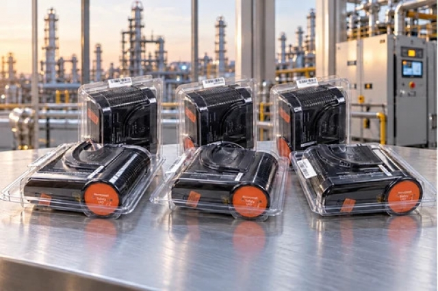
Review label, connector and mounting-thread photographs. Confirm New, original product condition and included mounting hardware; cable and input card are separate unless itemized.
Technical specifications for 200350-00-00-00
-
Manufacturer:Bently Nevada
-
Product Category:Machinery Monitoring Systems
-
Spare Part Number:200350-00-00-00
-
Weight:0.05 kg
-
Tariff Code:8537101190
-
Sensitivity:100 mV/g ±20%
-
Frequency range:0.5 to 10,000 Hz (±3 dB)
-
Measurement range:±50 g
-
Transverse sensitivity:≤7%
-
Amplitude linearity:±1%
-
Mounted resonant frequency:25 kHz
-
Broadband electrical noise:350 µg (1 to 10 kHz)
-
Excitation voltage:18 to 28 V DC; positive excitation only
-
Constant-current excitation:2 to 20 mA
-
Output bias voltage:8 to 12 V DC
-
Settling time:≤2.0 s within 1% of bias
-
Output impedance:<150 ohm
-
Discharge time constant:≥0.3 s
-
Case electrical isolation:>100 MΩ
-
Operating temperature:-54 to +121 °C
-
Shock survivability:5,000 g peak
-
Enclosure rating:IP68
-
Humidity condition:100% RH, condensing, non-submerged
-
Sensing element / geometry:Ceramic / shear
-
Housing / sealing:Stainless steel / welded hermetic
-
Mounting stud:1/4-28 stainless steel with brass tip
-
Mounting torque:2.7 to 6.8 N·m
-
Electrical connector:Top-mounted 2-pin MIL-C-5015
-
Approval option:00 - No approvals
Information
- Bently Nevada 200350-00-00-00 measures vibration transmitted to a bearing housing or machine casing. The mounting point must carry the vibration of interest for the acceleration reading to represent machine behavior.
Power interface: Positive 18-28 V DC, 2-20 mA constant current
Construction: Ceramic shear element in a welded stainless-steel case
Positive 18–28 V DC, 2–20 mA constant-current excitation is required; negative excitation is unsuitable. Output bias is 8–12 V DC, settling within 1% in no more than 2 seconds.
A top-mounted two-pin MIL-C-5015 connector separates cable removal from sensor mounting. The supplied 1/4-28 stud couples the case to the machine; inadequate contact can reduce amplitude and frequency response. The welded housing provides hermetic sealing and electrical case isolation.
200350-00-00-00 Official Datasheet Excerpt
Original 200350/200355 sensor description, electrical and environmental data, cable options and connection drawing. PDF · 6 pages.200350-00-00-00 Installation & Verification Guide
Apter Power field guide to mounting preparation, positive excitation, bias checks and acceleration-channel commissioning. PDF · 5 pages.
Measurement applications: The uses below concern casing acceleration. Suitability depends on the mounting location, structural vibration transmission and input configuration; the sensor is not a shaft-displacement probe.
Bearing-housing acceleration
Monitor acceleration transmitted to a bearing housing, using a mechanically sound mounting location aligned with the vibration of interest.Machine-casing vibration
Measure casing motion where the structural transmission path preserves relevant rotor vibration. The sensor does not directly measure shaft-relative displacement.Trendmaster Pro constant-current input
Connect through the supported Constant Current Direct Input Card 149811-02 with positive excitation and correctly configured sensor scaling.Trendmaster Pro seismic input
Use the supported Seismic Direct Input Card 164746-01, with the correct input power, acceleration scaling and measurement-channel configuration.
Supply 18 to 28 V DC at 2 to 20 mA constant current. Do not connect the 200350 sensor to negative excitation.
Use the correct 1/4-28 stud and a clean, flat machine surface. Apply 2.7 to 6.8 N·m mounting torque.
The splash-proof cable is not recommended for 200350. Check the standard two-conductor shielded cable and connector assignment.
Check for 8 to 12 V DC output bias after energization. Allow up to 2.0 seconds for settling within 1% of bias.
The final 00 option has no approvals. IP68 and a hermetic case do not establish hazardous-area approval.
Check sensor orientation, cable loading and receiving-channel sensitivity. Demonstrate acceleration response before returning the channel to service.
Alternative Names
Technical notes
Excitation polarity: Use a positive constant-current input providing 18 to 28 V DC and 2 to 20 mA. Negative excitation is not permitted for the 200350.
Measurement conditions: Specifications are referenced to +20 to +30 °C and 100 Hz unless stated otherwise. The 31 m cable recommendation assumes 50 g at 10 kHz and 200 pF/m cable capacitance.
Mounting and cable choice: Use 2.7 to 6.8 N·m mounting torque. The splash-proof cable is not recommended for this sensor; check the standard cable and approved mounting procedure.
Technical reference: Bently Nevada 200350 and 200355 Accelerometers, 164804 Rev. T; applicable sensor User Guide 168303.

FAQ View All FAQ
-
Can 200350-00-00-00 operate from a negative excitation supply?No. Use positive 18 to 28 V DC excitation with a constant current of 2 to 20 mA. The 200350 sensor must not be connected to a negative-excitation input; check the input-card power configuration before connection.
-
How should the 100 mV/g sensitivity of 200350-00-00-00 be used in channel scaling?Set the receiving acceleration channel to the sensor sensitivity. The nominal value is 100 mV/g with ±20% tolerance; where an individual calibration value is available, use it according to the monitoring-system setup procedure. Do not apply the tighter 200355 tolerance to this model.
-
Why can a poor mounting point reduce the response of 200350-00-00-00?The sensor measures acceleration transmitted through the machine casing or bearing housing. A flexible or unsuitable mounting location can attenuate vibration or introduce false signals. Use a prepared mounting surface and the specified stud, and apply 2.7 to 6.8 N·m mounting torque.
-
What bias and settling behavior should 200350-00-00-00 show after energization?The output bias should be 8 to 12 V DC, with settling to within 1% of bias in no more than 2.0 seconds under the specified conditions. A valid bias is an electrical check; verify the vibration response at the receiving channel as well.
-
Which frequencies can 200350-00-00-00 measure within its ±3 dB response band?The frequency range is 0.5 Hz to 10 kHz. Its 25 kHz mounted resonance is outside that measurement band and must not be used as the upper calibrated measurement frequency. Mounting and cable loading can affect the installed response.
-
How does cable capacitance affect a long connection to 200350-00-00-00?The recommended length is 31 m for a maximum vibration of 50 g at 10 kHz and cable capacitance of 200 pF/m. This is a conditional limit, not a universal cable allowance. Review cable capacitance, excitation and required high-frequency response for longer runs.
-
Can the splash-proof CB2W100 cable be used with 200350-00-00-00?The splash-proof cable is not recommended for the 200350 accelerometer. Review the standard 9571 unarmored or 84661 armored cable options with a two-socket connector and suitable length. Do not infer compatibility from connector appearance alone.
-
Does the IP68 rating of 200350-00-00-00 establish hazardous-area approval?No. IP68 describes enclosure protection, while the final 00 ordering option specifies no approvals. The environmental condition is 100% relative humidity, condensing and non-submerged. Do not treat this configuration as the separately approved 01 option.
Supporting new and legacy automation
-
Please try to be as accurate as possible with your search.
-
We can quote you on 1000s of specialist parts, even if they are not listed on our website.
-
We can't find any results for “”.
Related cases and sourcing guidance
View all case studiesYou May Also Like
Product Browsing History
-
Whatsapp: +86 18030235313
Send us a message. -
sales13@apterpower.com
Complete our online form. -
+86 18030235313
Speak to our team in your native language.