Speak to a sourcing specialist
sales13@apterpower.com

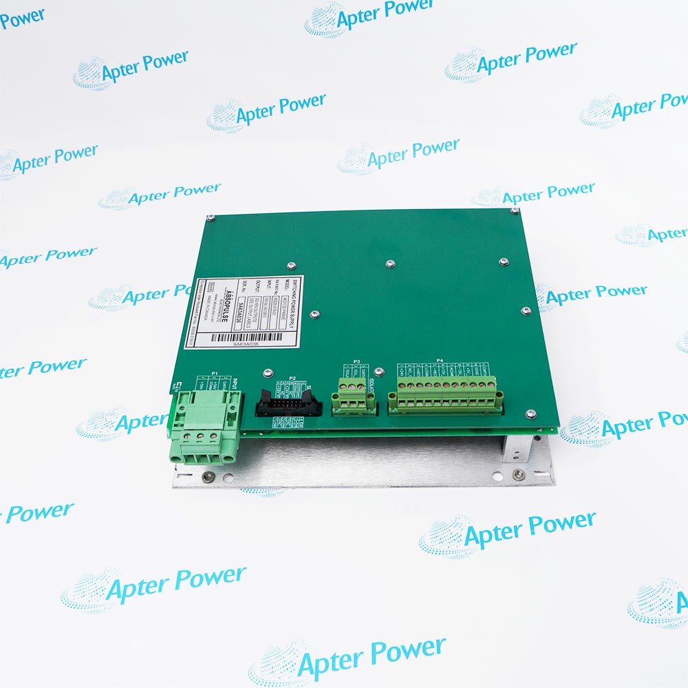
80026-529-01-R

AC DC Supply
Ships by Thursday, November 12
Product image is representative; revision or series may vary. Contact us to request a specific version.

Product Describe:

Allen-Bradley 80026-529-01-R provides a 56 VDC, 1000 W auxiliary output from a single-phase AC input.
  • Manufacturer part number
    80026-529-01-R
  • Shipping
    Swift global dispatch
  • Condition
    New, original product
  • Shipping size (est.)
    31.5cm x 12.8cm x 12.8cm
  • Country of Origin
    USA
Get a quick price for 80026-529-01-R
E-mail *
Mobile *
Company
Content *
Quantity *
Upload (gif, jpg, jpeg, png, bmp, doc, docx, xls, xlsx, ppt, pdf, csv)
For more information on how your data is processed and stored by Apterpower please read our privacy policy

What happens after you enquire

  • 0

    Review your reference

    Send the complete Allen-Bradley 80026-529-01-R reference, label photographs and required quantity. Include the host controller or drive and the actual supply connection diagram.

  • 1

    Confirm the offer

    Review the offered revision, condition, included items and documents against the confirmed installation.

  • 2

    Arrange dispatch

    Confirm quantity, dispatch date, lead-time start and delivery details in the quotation.

  • Match the complete marking

    Include the complete Allen-Bradley 80026-529-01-R marking and any hardware revision on the item. Include the host controller or drive and the actual supply connection diagram.

  • Check the offered item before ordering

    Request available label and connector photos. Have your maintenance team compare the offered 80026-529-01-R with the installed equipment and applicable Allen-Bradley documentation.

Technical specifications for 80026-529-01-R

  • Manufacturer:
    Allen-Bradley
  • Product Category:
    General Automation
  • Spare Part Number:
    80026-529-01-R
  • Weight:
    4.4 kg
  • Tariff Code:
    8537101190
  • Input phase:
    Single phase
  • Nominal DC output:
    56 VDC
  • Power rating:
    1000 W
  • Drive DC-fail threshold:
    Below 49 VDC
  • Drive AC-fail threshold:
    Below 85 Vrms
  • DC status inputs:
    ACB J18-J21; installed supply positions
  • 56 V monitoring:
    ACB J15

Information

Overview Downloads Applications / Compatibility Product Precautions
  • Allen-Bradley 80026-529-01-R serves a defined point in the PowerFlex 7000 auxiliary power path. Separating the source, connections and monitored output helps locate the actual cause of a supply-related fault.
Input phase: Single phase
Nominal DC output: 56 VDC
Power rating: 1000 W
The selected converter is the 1000 W, single-phase-input 56 VDC source in the PowerFlex 7000 auxiliary-power system. Other source ratings are separate spare selections; the installed control-power wiring and supply allocation govern its application.

The drive can monitor multiple AC/DC sources by position. AC Fail identifies a low input-control-voltage condition, while DC Fail uses the individual converter output sensing circuit. The diagnostic thresholds of 85 Vrms and 49 VDC describe drive fault detection rather than universal supply nameplate limits.

Troubleshooting compares physical input/output measurements, ACB status wiring and the drive metering values. The converter cooling fan must operate. A failed fan or sustained output loss must be resolved before returning the auxiliary power circuit to service.
Controller platform reference: PowerFlex 7000 auxiliary power. Verify the installed supply and monitored connections.
The original technical excerpt for Allen-Bradley 80026-529-01-R covers exact supply identification and applicable fault investigation. The separate installation guide covers power-path identification, connection restoration and diagnostic comparison.
Original manufacturer pages retain their technical context. Use the Apter Power guide with the applicable manufacturer instructions and approved installation design.
Prepare Allen-Bradley 80026-529-01-R for its configured installation using these checks.
Isolate AC and DC energy

Use the approved drive isolation and discharge procedure for both the control input and downstream DC circuit. Prove safe conditions before disconnecting the converter.

Inspect cooling and connectors

Check the input, DC output and fault-monitor connectors for seating or damage. Keep the airflow path clear and inspect the fan condition.

Restore the exact supply

Match the single-phase 1000 W source and retained wiring. Do not select another power rating solely because its output is also 56 VDC.

Verify energization conditions

Under the prescribed test procedure, confirm the correct input control power and measure the source output. The fault thresholds are not substitutes for the input nameplate.

Check output and status together

Compare physical output with the 49 VDC DC-fail threshold and the assigned ACB status input. Investigate inconsistent status wiring before replacing another component.

Confirm cooling operation

Verify that the internal cooling fan runs as required. A failed fan must be corrected by the specified supply replacement action.

Alternative Names

80026 529 01 R Allen-Bradley 80026-529-01-R

Technical notes

Status versus power: A supply status signal and a measured DC output answer different diagnostic questions. Check both when investigating an AC/DC supply fault.

Cooling dependency: Include the power-supply fan and airflow path in the service check. Restored output voltage alone does not prove acceptable cooling during operation.


FAQ View All FAQ

  • What distinguishes 80026-529-01-R from the other 56 VDC supply selections?
    It is the single-phase-input, 1000 W AC/DC selection. A 300 W or 1500 W source is a different part selection.
  • Does the 85 Vrms diagnostic threshold specify the complete input rating of 80026-529-01-R?
    No. It is the drive AC-fail detection threshold. The actual control supply and input rating must match the installed converter and drive drawings.
  • When is a DC-fail signal associated with 80026-529-01-R generated?
    The AC/DC converter DC-fail condition is triggered when its monitored output drops below 49 VDC.
  • How does the drive distinguish status from several supplies including 80026-529-01-R?
    It assigns supply positions and monitors their DC-fail signals through ACB inputs J18, J19, J20 and J21 as configured.
  • Why inspect the internal fan when diagnosing 80026-529-01-R?
    The fan is required for converter cooling. The drive troubleshooting procedure calls for replacement of a supply whose internal fan is not operational.
  • Can 80026-529-01-R be declared faulty from a status signal alone?
    No. Verify that the source is energized, measure its output, and compare the fault-detection wiring and signal levels with the drive drawings.
  • What healthy signal example is given for the DC-fail circuit of 80026-529-01-R?
    At the example ACB J18 terminals 2-3, the diagnostic signal is 5 VDC when healthy and 0 V when faulted. Apply the correct terminal assignment for the installed supply position.
  • Which output should be compared with the drive metering value for 80026-529-01-R?
    Compare the physical 56 VDC source output with the corresponding monitoring circuit and metering indication. Resolve sensing-wiring discrepancies before condemning the converter.
SPEAK TO OUR TEAM
Let’s find the right solution for you.
Send us the part number, quantity and delivery destination. Our team will help confirm availability and lead time.
  • Whatsapp: +86 18030235313

    Send us a message.
  • sales13@apterpower.com

    Complete our online form.
  • +86 18030235313

    Speak to our team in your native language.