-
Match the complete marking
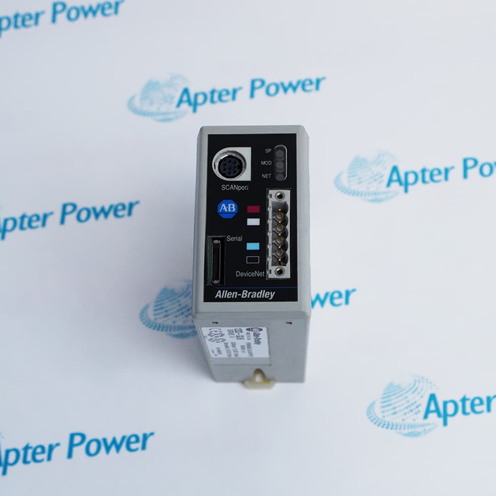
Include the complete Allen-Bradley 80026-044-02 marking and any hardware revision on the item. Include the host controller or drive and the actual supply connection diagram.
-
Check the offered item before ordering
Request available label and connector photos. Have your maintenance team compare the offered 80026-044-02 with the installed equipment and applicable Allen-Bradley documentation.
Technical specifications for 80026-044-02
-
Manufacturer:Allen-Bradley
-
Product Category:General Automation
-
Spare Part Number:80026-044-02
-
Weight:4 kg
-
Tariff Code:8537101190
-
Nominal input:50 VDC
-
Input diagnostic range:50 VDC +/-8 VDC
-
Isolated outputs:6
-
Nominal output:20 VDC per channel
-
Output verification:20 VDC +/-1%
-
LED low threshold:Below 18 VDC
-
Construction:Epoxy-encapsulated circuitry
Information
- Allen-Bradley 80026-044-02 serves a defined point in the MV SMC gate-drive power path. Separating the source, connections and monitored output helps locate the actual cause of a supply-related fault.
Input diagnostic range: 50 VDC +/-8 VDC
Isolated outputs: 6
The board is supplied from nominal 50 VDC. Each output module has a green indication for a healthy 20 VDC output; an extinguished indication corresponds to output below 18 VDC. If the group is dark, inspect the common input and connections before treating all channels as failed.
The circuitry is epoxy encapsulated and has no internal field-test points or adjustments. The service test checks each accessible output at 20 VDC within +/-1%. A failed output requires replacement of the board rather than internal repair.
80026-044-02 Official Technical Excerpt
The original technical excerpt for Allen-Bradley 80026-044-02 covers exact supply identification and applicable fault investigation. PDF · 5 pages.80026-044-02 Installation & Verification Guide
Apter Power installation and verification guide covering power-path identification, connection restoration and diagnostic comparison. PDF · 5 pages.
Application scope: Use the exact supply selection within the stated platform. Similar output voltages do not establish compatibility with a different source or gate-drive board.
Auxiliary source verification
Capture which green channel indicators are lit or dark and the operating condition when the fault occurred. Preserve that evidence before removing power.Controlled circuit replacement
Use appropriate ESD handling and support the board at its mechanical mounting. Do not open encapsulation or attempt internal adjustment.Diagnostic comparison
Using the authorized safe test procedure, confirm the board input is 50 VDC +/-8 VDC. Resolve a missing common feed before investigating individual outputs.System recovery
All healthy channel indicators should be illuminated. Investigate a dark indicator, bad connection or low output; replace the board if an output module is defective.
Remove main and control energy using the approved MV SMC procedure and prove the circuits safe before touching boards, motor circuits or control devices.
Use appropriate ESD handling and support the board at its mechanical mounting. Do not open encapsulation or attempt internal adjustment.
Reconnect each labeled output to its retained gate-drive position. Check seating and the common input connection without interchanging isolated circuits.
Using the authorized safe test procedure, confirm the board input is 50 VDC +/-8 VDC. Resolve a missing common feed before investigating individual outputs.
Check pin 1 to pin 2 of each of the six outputs using the prescribed measurement arrangement. Compare each result with 20 VDC +/-1%.
All healthy channel indicators should be illuminated. Investigate a dark indicator, bad connection or low output; replace the board if an output module is defective.
Alternative Names
Technical notes
Channel comparison: Measure the isolated outputs individually. One healthy channel does not establish that all six gate-power paths are available.
Input-versus-output fault: If all channel indicators are dark, establish the common input condition before attributing the failure to six separate output modules.

FAQ View All FAQ
-
How many isolated gate outputs does 80026-044-02 provide?Six isolated outputs supply the associated gate-drive circuits. Record the channel assignments before disconnecting them.
-
What input is expected when diagnosing 80026-044-02?The MV SMC diagnostic procedure expects nominal 50 VDC with an allowable check range of +/-8 VDC at the board input.
-
Why might every indicator on 80026-044-02 be dark?A missing input source or bad input connection can affect the whole board. Verify the common 50 VDC feed before diagnosing six independent output failures.
-
What does an extinguished channel LED on 80026-044-02 indicate?Its output voltage is below 18 VDC. Compare the indication with a controlled measurement and connection inspection.
-
Which voltage tolerance is used to verify the outputs of 80026-044-02?Each of the six outputs should measure 20 VDC within +/-1% under the prescribed test procedure.
-
Can a faulty output module inside 80026-044-02 be repaired in the field?No. The circuitry is encapsulated, with no internal test points or adjustments. A failed channel calls for board replacement.
-
Why is continuous gate power from 80026-044-02 needed for optional stopping modes?Applicable soft-stop and pump-control arrangements use the isolated supply to maintain gate-drive power rather than relying only on power derived from the operating snubber circuit.
-
How are multiple 80026-044-02 boards handled during a controller test?Test and record all six outputs on every installed board. One board passing does not establish the condition of other boards or their assigned gate circuits.
Supporting new and legacy automation
-
Please try to be as accurate as possible with your search.
-
We can quote you on 1000s of specialist parts, even if they are not listed on our website.
-
We can't find any results for “”.
Related cases and sourcing guidance
View all case studiesYou May Also Like
Product Browsing History
-
Whatsapp: +86 18030235313
Send us a message. -
sales13@apterpower.com
Complete our online form. -
+86 18030235313
Speak to our team in your native language.